
Installation Instructions User Manual

18 SLC™ 500 4-Channel Thermocouple/mV Input Module
Publication 1746-IN010D-EN-P - June 2004
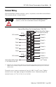
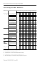
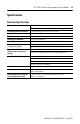
Channel Configuration Word - Bit Definitions
Define To Select
Make these bit settings in the Channel Configuration Word
(1)
(1) Bit settings other than those shown in the table are invalid.
15–12
(2)
(2) Ensure unused bits 12-15 are always set to zeros.
11109876543210
Input type Thermocouple Type J
Not Used
0000
Thermocouple Type K
0001
Thermocouple Type T
0010
Thermocouple Type E
0011
Thermocouple Type R
0100
Thermocouple Type S
0101
Thermocouple Type B
0110
Thermocouple Type N
0111
±50mV
1000
±100mV
1001
CJC temperature
1111
Data format
Engineering units 1
(3)
(3) For engineering units x 1, values are expressed in 0.1 degrees or 0.01 mV.
00
Engineering units 10
(4)
(4) For engineering units x 10, values are expressed in 1.0 degrees or 0.1 mV.
01
Scaled-for-PID 10
Proportional Counts 11
Open circuit Zero 00
Upscale 01
Downscale 10
Temperature
units
Degrees C
(5)
(5) When millivolt input type is selected, the bit setting for temperature units is ignored.
0
Degrees F
(5)
1
Channel
filter
frequency
10 Hz
00
50 Hz 01
60 Hz 10
250 Hz 11
Channel
enable
Channel Disabled 0
Channel Enabled 1