
Installation Instructions User Manual

14 SLC™ 500 4-Channel Thermocouple/mV Input Module
Publication 1746-IN010D-EN-P - June 2004
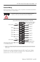
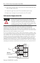
– If millivolt inputs are used, the terminal should be biased to a level
within 2V of the signal of interest. Use 10KΩ resistors to create a resistive
voltage divider as shown in the following circuit diagram.
• Ground the shield drain wire at one end only. The preferred location is to
the same point as the sensor ground reference.
– For grounded thermocouples or mV sensors, this is at the sensor.
– For insulated/ungrounded thermocouples, this is at the module.
– Refer to IEEE Std. 518, Section 6.4.2.7 or contact your sensor
manufacturer for additional details.
• If it is necessary to connect the shield at the module, each input channel has
a convenient shield connection screw terminal that provides a connection to
chassis ground. All shields are internally connected, so any shield terminal
can be used with channels 0-3. For maximum noise reduction, one shield
terminal must be connected to earth ground potential, i.e. mounting bolt on
1746 chassis.
TIP
The Series A 1746-NT4 does not have an ANALOG COM
terminal and cannot be used with multiple grounded and/or
exposed thermocouples that touch electrically conductive
material. The Series A can be used with a single grounded
and/or exposed thermocouple that touches electrically
conductive material, or multiple grounded thermocouples that
have the protective sheath made of an electrically
non-conductive material such as ceramic.
+
-
+
Strain Gauge
Bridge
NT4
Vcc
10K Ω
10K Ω
variable
fixed
fixed
fixed
Input
(CHL 0, CHL 1, CHL
2, CHL 3)
Analog Com