
Installation Instructions User Manual

10 SLC™ 500 4-Channel Thermocouple/mV Input Module
Publication 1746-IN010D-EN-P - June 2004
Module Installation and Removal
Module Installation Procedure
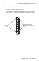
1. Align the circuit board of the thermocouple module with the card guides
located at the top and bottom of the chassis.
2. Slide the module into the chassis until both top and bottom retaining clips
are secured. Apply firm even pressure on the module to attach it to its
backplane connector. Never force the module into the slot.
3. Cover all unused slots with the Card Slot Filler, Catalog Number 1746-N2.
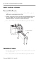
Module Removal Procedure
1. Press the releases at the top and bottom of the module and slide the module
out of the chassis slot.
2. Cover all unused slots with the Card Slot Filler, Catalog Number 1746-N2.
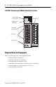
Top and Bottom Module
Card
Guide