
User Manual Owner's manual


Publication 1746-UM007C-EN-P - July 2004
Module Diagnostics and Troubleshooting 7-3
LED Indicators
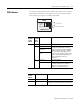
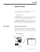
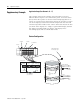
The thermocouple module has five LEDs. Four of these are channel
status LEDs numbered to correspond to each of the thermocouple’s
input channels, and one is a module status LED.
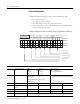
If
Module
Status
LED is:
And
Channel
Status
LED is:
Indicated Condition: Corrective action:
On On Channel Enabled No action required.
Blinking Open Circuit Condition To determine the exact error, check the
error bits in the input image. Check the
channel configuration word for valid data.
Make sure that the input type is indicated
correctly in bits 0-3, and that the open
circuit selection state (bits 6 and 7) is valid.
Refer to the troubleshooting flowchart on
page 7-6 and chapter 5 for more
information.
Out-of-Range
Condition
Channel Configuration
Error
Off Power-Up No action required.
Channel Not Enabled No action required. For an example of how
to enable a channel refer to chapter 2,
Quick Start for Experienced Users, or
chapter 6, Programming Examples.
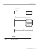
If Module
Status
LED is:
Indicated condition: Corrective action:
On Proper Operation No action required.
Off Module Fault Cycle power. If condition persists, call your local
distributor or Rockwell Automation for assistance.
0
1
2
3
INPUT
Channel LEDs
Module Status LED
MODULE STATUS
CHANNEL
THERMOCOUPLE/mV
STATUS