
User Manual Owner's manual

Publication 1746-UM007C-EN-P - July 2004
4-2 Preliminary Operating Considerations
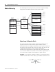
Module Addressing
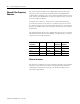
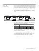
The following memory map shows you how the output and input
image tables are defined for the thermocouple module.
Output Image-Configuration Words
The 8-word, thermocouple module output image (defined as the
output from the CPU to the thermocouple module) contains
information that you configure to define the way a specific channel on
the thermocouple module will work. These words take the place of
configuration DIP switches on the module. Although the
thermocouple output image is eight words long, only output words
0-3 are used to define the operation of the module; output words 4-7
are not used. Each output word configures a single channel.
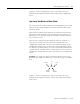
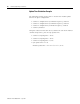
Example - If you want to configure channel 2 on the thermocouple
module located in slot 4 in the chassis, your address would be O:4.2.
Channel 0 Configuration W
ord
Channel 1 Configuration W
ord
Channel 2 Configuration W
ord
Channel 3 Configuration W
ord
Channel 0 Data W
ord
Channel 1 Data W
ord
Channel 2 Data W
ord
Channel 3 Data W
ord
Channel 0 Status W
ord
Channel 1 Status W
ord
Channel 2 Status W
ord
Channel 3 Status W
ord
W
ords 4 7
(not defined)
Output Image
8 W
ords
Input Image
8 W
ords
Output Image
Input Image
Output
Scan
Input
Scan
Output Image
Input Image
Slot e
Slot e
SLC 5/0X
Data Files
Thermocouple
Module
Image Table
Bit
15
Bit 0
Bit 15
Bit 0
W
ord 0
W
ord 1
W
ord 2
W
ord 3
W
ord 7
W
ord 0
W
ord 1
W
ord 2
W
ord 3
W
ord 4
W
ord 5
W
ord 6
W
ord 7
Address
Address
O:e.0
O:e.1
O:e.2
O:e.3
O:e.7
I:e.0
I:e.1
I:e.2
I:e.3
I:e.4
I:e.5
I:e.6
I:e.7
(Class 1)
_
•
•
•
•
•
•
O : 4 . 2
File Type
Slot
Word
Element
Delimiter
Word
Delimiter