
User Manual Owner's manual


Publication 1746-UM007C-EN-P - July 2004
Quick Start for Experienced Users 2-7
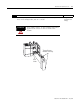
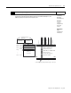
9. Go through the system start-up proceedure. Reference
Apply power. Download your program to the SLC and put the controller into Run mode. In this
example during a normal start up, the module status LED and channel status 0 LED turn on.
Chapter 7
(Module
Diagnostics and
Troubleshooting)
0
1
2
3
INPUT
Channel LEDs
Module Status LED
MODULE STATUS
CHANNEL
THERMOCOUPLE/mV
STATUS
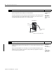
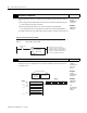
10. Check module operation. Reference
(Optional) Monitor the status of input channel 0 to determine its configuration setting and
operational status. This is useful for troubleshooting when the blinking channel LED indicates
that an error has occurred. If the Module Status LED is off, or if the Channel 0 LED is off or
blinking, refer to chapter 7.
Chapter 5
(Channel
Configuration,
Data, and
Status)
Chapter 6
(Ladder
Programming
Examples)
Chapter 8
(Application
Examples)
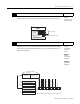
Channel 1 Data W
ord
Channel 2 Data W
ord
Channel 3 Data W
ord
Output Image
SLC 500 Controller
Data Files
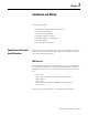
Bit
15
Bit 0
W
ord 1
W
ord 2
W
ord 3
Address
I:1.4
Input Image
Channel 0 Data W
ordW
ord 0
W
ord 7
(8 words)
Channel 1 Status W
ord
Channel 2 Status W
ord
Channel 3 Status W
ord
Channel 0 Status W
ord
0
0
0
0
1
0
0
0
0
0
0
0
0
0
0
0
Input
Type
Data Format
Open Circuit
Type
T
emperature Units
Filter Frequency
Channel Status
Open Circuit Error
Under Range Error
Over Range Error
Configuration Error
For this example, during normal operation only bit 11 is set.
•
•