
User Manual Owner's manual


Publication 1746-UM007C-EN-P - July 2004
2-2 Quick Start for Experienced Users
Installation Procedures
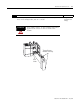
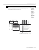
1. Check the contents of shipping box. Reference
Unpack the shipping box making sure that the contents include:
• thermocouple input module (Catalog Number 1746-NT4)
• removeable terminal block (factory installed on module) with CJC sensors attached.
• installation instructions (publication 1746-IN010)
If the contents are incomplete, call your local Allen-Bradley representative for assistance.
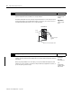
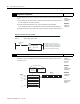
2. Ensure your chassis supports placement of the 1746-NT4 module Reference
Review the power requirements of your system to see that your chassis supports placement of the
thermocouple input module.
• For modular style systems, calculate the total load on the system power supply using the
procedure described in the SLC 500 Modular Hardware Style User Manual (Publication
Number 1747-UM011) or the SLC 500 Modular Chassis and Power Supplies Technical Data
(Publication Number 1746-TD003).
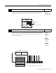
• The fixed, 2-slot chassis supports 2 thermocouple input modules. If combining a
thermocouple module with a different module, refer to the module compatibility table
found in chapter 3.
Chapter 3
(Installion and
Wiring
Appendix A
(Specifications)