SLC™ 500 4-Channel Thermocouple/mV Input Module (Catalog Number 1746-NT4, Series B) User Manual
Important User Information Solid state equipment has operational characteristics differing from those of electromechanical equipment. Safety Guidelines for the Application, Installation and Maintenance of Solid State Controls (Publication SGI-1.1 available from your local Rockwell Automation sales office or online at http://www.ab.com/manuals/gi) describes some important differences between solid state equipment and hard-wired electromechanical devices.
Summary of Changes The information below summarizes the changes to this manual since the last printing. To help you find new and updated information in this release of the manual, we have included change bars as shown to the right of this paragraph. For information on: See page: Changes to the SLC™ 500 Thermocouple/mV Input Module. throughout manual Using RSLogix™ 500 to configure the NT4 module. 2-4, 5-2, 6-1, and Appendix E Maintaining the ambient temperature surrounding the SLC 500 above 3°C (37.
2 Summary of Changes Publication 1746-UM007C-EN-P - July 2004
Table of Contents Preface Who Should Use this Manual. . . . . . . . . . . . . . . . Purpose of this Manual . . . . . . . . . . . . . . . . . . . . Related Documentation . . . . . . . . . . . . . . . . . Your Questions or Comments on this Manual . Common Techniques Used in this Manual . . . . . . . . . . . . . . . . . . . . . . . . . . . . . . . . . . . . . . . . . P-1 P-1 P-2 P-3 P-3 . . . . . . . . . . . . . . . . . . . . . . . . . . . . . . . . . . . . . . . . . . . . . . . . . . . . . . .
Table of Contents ii Effective Resolution . . . . . . . . . . . . . . . . . . . . . . . . . Channel Cut-Off Frequency . . . . . . . . . . . . . . . . . . . Channel Step Response . . . . . . . . . . . . . . . . . . . . . . Update Time. . . . . . . . . . . . . . . . . . . . . . . . . . . . . . . . . Update Time Calculation Example . . . . . . . . . . . . . . Channel Turn-On, Turn-Off, and Reconfiguration Times . Response to Slot Disabling . . . . . . . . . . . . . . . . . . . . . . Input Response . . . . .
Table of Contents iii Chapter 7 Module Diagnostics and Troubleshooting Module Operation vs Channel Operation . Power-up Diagnostics . . . . . . . . . . . . . . . Channel Diagnostics . . . . . . . . . . . . . . . . LED Indicators . . . . . . . . . . . . . . . . . . . . Channel Status LEDs (Green) . . . . . . . Invalid Channel Configuration . . . . . . Open Circuit Detection . . . . . . . . . . . Out-Of-Range Detection. . . . . . . . . . . Module Status LED (Green) . . . . . . . .
Table of Contents iv (Copper vs. Copper-Nickel ) . . . . . . . . E Type Thermocouple. . . . . . . . . . . . . . . . . . . . . . . . . . (Nickel-Chromium vs. Copper-Nickel ) . S and R Type Thermocouples . . . . . . . . . . . . . . . . . . . . S (Platinum-10% Rhodium vs. Platinum) R (Platinum-13% Rhodium vs. Platinum) . . . . . . . . . Appendix D Thermocouple Types Appendix E Configuring the 1746-NT4 Module with RSLogix 500 Glossary Index Publication 1746-UM007C-EN-P - July 2004 .
Preface Read this preface to familiarize yourself with the rest of the manual. The preface includes: • Who Should Use this Manual • Purpose of this Manual • Common Techniques Used in this Manual Who Should Use this Manual Use this manual if you are responsible for designing, installing, programming, or troubleshooting control systems that use SLC 500 4-Channel Thermocouple/mV Input Module. You should have a basic understanding of electrical circuitry and familiarity with relay logic.
2 Preface Related Documentation The following documents contain additional information concerning Rockwell Automation products. To obtain a copy, contact your local Rockwell Automation office or distributor. For Read this Document Document Number In-depth information on the SLC Instruction Set. SLC 500 Instruction Set Reference Manual 1747-RM001 A description on how to install and use your Modular SLC 500 programmable controller.
Preface 3 If you would like a manual, you can: • download an electronic version from the internet at: – www.theautomationbookstore.com – http://www.ab.com/manuals • order a printed manual by: – contacting your local distributor or Rockwell Automation representative – visiting www.theautomationbookstore.com – calling 1.800.963.9548 (USA/Canada) or 001.330.725.
4 Preface Publication 1746-UM007C-EN-P - July 2004
Chapter 1 Overview This chapter describes the thermocouple/millivolt module and explains how the SLC controller gathers thermocouple or millivolt initiated analog input from the module. This chapter includes: • General Description • System Overview General Description The thermocouple/mV module receives and stores digitally converted thermocouple and/or millivolt (mV) analog data into its image table for retrieval by all fixed and modular SLC 500 processors.
1-2 Overview Hardware Features The thermocouple module fits into any single-slot, except the processor slot (0), in either an SLC 500 modular system or an SLC 500 fixed system expansion chassis (1746-A2). It is a Class 1 module (uses 8 input words and 8 output words). It interfaces to thermocouple types J, K, T, E, R, S, B, and N, and supports direct ±50 mV and ±100 mV analog input signals. The module requires the use of Block Transfer in a remote configuration.
Overview Hardware Function Channel Status LED Indicators Display operating and fault status of channels 0, 1, 2, and 3 Module Status LED Displays module operating and fault status Side Label (Nameplate) Provides module information Removable Terminal Block Provides physical connection to input devices. It is color coded green.
1-4 Overview Each individual channel on the thermocouple module can receive input signals from thermocouple sensors or mV analog input devices. You configure each channel to accept either input. When configured for thermocouple input types, the thermocouple module converts the analog input voltages into cold-junction compensated and linearized, digital temperature readings. The 1746-NT4 uses the National Bureau of Standards (NBS) Monograph 125 and 161 based on IPTS-68 for thermocouple linearization.
Overview 1-5 Module Operation The thermocouple module input circuitry consists of four differential analog inputs multiplexed into a single analog-to-digital (A/D) convertor. The mux circuitry also continuously samples the CJC A and CJC B sensors and compensates for temperature changes at the cold junction (terminal block). The figure on the following page shows a block diagram for the analog input circuitry. The A/D convertor reads the selected input signal and converts it to a digital value.
1-6 Overview Input Circuit Block Diagram Input Circuit Block Diagram Terminal Block Module Circuitry + CJCA Sensor Open Circuit Detection + Channel 0 ungrounded thermocouple Shield User-Selected Filter Frequency + Channel 1 Shield grounded thermocouple within 2V* Multiplexer + Channel 2 Analog to Digital Convertor Digital Filter Digital Value Shield grounded thermocouple within 2V* + Channel 3 - *See Important note below .
Overview ATTENTION 1-7 The possibility exists that grounded or exposed thermocouples can become shorted to a potential greater than that of the thermocouple itself. Due to possible shock hazard, care should be taken when wiring these types of thermocouples. Refer to Appendix D for more details. Linear Millivolt Device Compatibility A large number of millivolt devices may be used with the 1746-NT4 module. For this reason we do not specify compatibility with any particular device.
1-8 Overview Publication 1746-UM007C-EN-P - July 2004
Chapter 2 Quick Start for Experienced Users This chapter can help you to get started using the NT4 4-channel thermocouple/mV module. The procedures are based on the assumption that you have an understanding of SLC 500 products. You should understand electronic process control and be able to interpret the ladder logic instructions required to generate the electronic signals that control your application.
2-2 Quick Start for Experienced Users Installation Procedures 1. Check the contents of shipping box. Reference Unpack the shipping box making sure that the contents include: • thermocouple input module (Catalog Number 1746-NT4) • removeable terminal block (factory installed on module) with CJC sensors attached. • installation instructions (publication 1746-IN010) If the contents are incomplete, call your local Allen-Bradley representative for assistance. 2.
Quick Start for Experienced Users 3. Insert the 1746-NT4 module into the chassis Reference Make sure system power is off; then insert the thermocouple input module into your 1746 chassis. In this example procedure, local slot 1 is selected. ATTENTION 2-3 Chapter 3 (Installation and Wiring) Never install, remove, or wire modules with power applied to the chassis or devices wired to the module.
2-4 Quick Start for Experienced Users 4. Connect the thermocouple wires Reference Connect thermocouple wires to channel 0 on the module’s terminal block. Make sure both cold junction compensation (CJC) assemblies are securely attached. Ground the shield drain wire at one end only. The preferred location is to the same point as the sensor ground reference. For grounded thermocouples or mV sensors, this is at the sensor. For insulated/ungrounded thermocouples, this is at the NT4 module.
Quick Start for Experienced Users Determine the operating parameters. Reference Determine the operating parameters for channel 0. This example shows the channel 0 configuration word defined with all defaults (0) except for channel enable (bit 11). The addressing reflects the location of the module as slot 1. Chapter 4 (Preliminary Operating Considerations) Chapter 5 (Channel Configuration, Data, and Status) O:1.0 O:1.1 O:1.2 O:1.
2-6 Quick Start for Experienced Users 7. Reference Program the configuration. Do the programming necessary to establish the new configuration word setting in the previous step. 1. Create integer file N10. Integer file N10 should contain one element for each channel used. (For this example we only need one, N10:0.) 2. Enter the configuration parameters from step 6 for channel 0 into integer N10:0. In this example all the bits of N10:0 will be zero except for the channel enable (N10:0/11). 3.
Quick Start for Experienced Users 9. Go through the system start-up proceedure. 2-7 Reference Apply power. Download your program to the SLC and put the controller into Run mode. In this example during a normal start up, the module status LED and channel status 0 LED turn on. Chapter 7 (Module Diagnostics and Troubleshooting) INPUT CHANNEL STATUS 0 2 1 3 Channel LEDs Module Status LED MODULE STATUS THERMOCOUPLE/mV Check module operation.
2-8 Quick Start for Experienced Users Publication 1746-UM007C-EN-P - July 2004
Chapter 3 Installation and Wiring This chapter provides: • • • • • • • Compliance to European Union Directives Compliance to European Union Directives Electrostatic Discharge NT4 Power Requirements Module Location in Chassis Module Installation and Removal Terminal Wiring Thermocouple Calibration If this product has the CE mark it is approved for installation within the European Union and EEA regions. It has been designed and tested to meet the following directives.
3-2 Installation and Wiring Electrostatic Discharge Electrostatic discharge can damage semiconductor devices inside this module if you touch backplane connector pins. Guard against electrostatic damage by observing the precautions listed next. ATTENTION Electrostatic discharge can degrade performance or cause permanent damage. Handle the module as stated below. • Wear an approved wrist strap grounding device when handling the module.
Installation and Wiring Module Location in Chassis 3-3 Place your thermocouple module in any slot of an SLC 500 modular, or modular expansion chassis, except for the extreme left slot (slot 0) in the first chassis. This slot is reserved for the processor or adapter. Fixed Expansion Chassis Considerations IMPORTANT The 2-slot, SLC 500 fixed I/O expansion chassis (1746-A2) will support only specific combinations of modules.
3-4 Installation and Wiring 1746- NT4 5V dc Amps 24V dc Amps IM16 x 0.085 N/A OA8 x 0.185 N/A OA16 x 0.370 N/A OAP12 x 0.370 N/A IB8 x 0.050 N/A IB16 x 0.085 N/A IV8 x 0.050 N/A IV16 x 0.085 N/A IG16 x 0.140 N/A OV8 x 0.135 N/A OV16 x 0.270 N/A OB8 x 0.135 N/A OBP8 x 0.135 N/A OG16 x 0.180 N/A OW4 x 0.045 0.045 OW8 x 0.085 0.090 0.170 0.180 OW16 Publication 1746-UM007C-EN-P - July 2004 IO4 x 0.030 0.025 IO8 x 0.060 0.
Installation and Wiring 1746- NT4 5V dc Amps 24V dc Amps NO4V x 0.055 0.145 ITB16 x 0.085 N/A ITV16 x 0.085 N/A IC16 x 0.085 N/A KE x 0.150 0.040 KEn x 0.150 0.145 OBP16 x 0.250 N/A OVP16 x 0.250 N/A NT4 x 0.060 0.040 NR4 x 0.050 0.050 HSTP1 x 0.020 N/A 3-5 General Considerations Most applications require installation in an industrial enclosure to reduce the effects of electrical interference.
3-6 Installation and Wiring Terminal Block Removal ATTENTION Never install, remove, or wire modules with power applied to the chassis or devices wired to the module. To remove the terminal block: 1. Loosen the two terminal block release screws. 2. Grasp the terminal block at the top and bottom and pull outward and down. When removing or installing the terminal block be careful not to damage the CJC sensors. CJC Sensors Terminal Block Release Screws Module Installation Procedure 1.
Installation and Wiring 3-7 3. Cover all unused slots with the Card Slot Filler, Catalog Number 1746-N2. Top and Bottom Module Release(s) Card Guide Module Removal Procedure 1. Press the releases at the top and bottom of the module and slide the module out of the chassis slot. 2. Cover all unused slots with the Card Slot Filler, Catalog Number 1746-N2. Terminal Wiring The thermocouple module contains a green, 18-position, removable terminal block. The terminal pin-out is shown on page 3-8.
3-8 Installation and Wiring (Terminal Block Spare Part Catalog Number 1746-RT32) Release Screw CJC A+ CJC Assembly CJC A _ Channel 0+ Channel 0 _ Shield Channel 1+ Shield Channel 1 _ Shield Channel 2+ Shield Channel 2 _ Shield CJC B _ CJC Assembly CJC B+ Release Screw Channel 3+ Channel 3 _ Analog Common [see below] Replacing a Series A thermocouple module with a Series B module requires that the bottom right terminal (which was SHIELD on Series A modules) no longer be connected to CHASSIS GROUND
Installation and Wiring 3-9 • To ensure proper operation and high immunity to electrical noise, always use Belden™ 8761 (shielded, twisted pair) or equivalent wire for millivolt sensors or shielded, twisted pair thermocouple extension lead wire specified by the thermocouple manufacturer for the thermocouple type you are using. Using the incorrect thermocouple extension wire type or not following the correct polarity convention will cause invalid readings.
3-10 Installation and Wiring • If it is necessary to connect the shield at the module, each input channel has a convenient shield connection screw terminal that provides a connection to chassis ground. All shields are internally connected, so any shield terminal can be used with channels 0-3. For maximum noise reduction, one shield terminal must be connected to earth ground potential, i.e. mounting bolt on 1746 chassis. • Tighten terminal screws using a flat or cross-head screwdriver.
Installation and Wiring 3-11 Wiring Input Devices to the NT4 After the thermocouple module is properly installed in the chassis, follow the wiring procedure below using the proper thermocouple extension cable, or Belden 8761 for non-thermocouple applications. Cable (Cut foil shield and drain wire; then insulate at cable end.) Signal Wire Signal Wire Signal Wire Drain Wire Foil Shield (Twist together, shrink wrap, and connect to earth ground.) Signal Wire To wire your NT4 module: 1.
3-12 Installation and Wiring Cold Junction Compensation (CJC) Do not remove or loosen the cold junction compensating thermistor assemblies located between the two upper and lower CJC terminals on the terminal block. Both thermistor assemblies are critical to ensure accurate thermocouple input readings at each channel. The module will not operate in the thermocouple mode if either assembly is removed.
Installation and Wiring Thermocouple Calibration 3-13 The thermocouple module is initially calibrated at the factory. The module also has an auto calibration function. Auto calibration compensates for offset and gain drift of the A/D converter caused by temperature change within the module. An internal, high precision, low drift voltage and system ground reference is used for this purpose. No external, user supplied device is required for autocalibration.
3-14 Installation and Wiring Publication 1746-UM007C-EN-P - July 2004
Chapter 4 Preliminary Operating Considerations This chapter explains how the thermocouple module and the SLC processor communicate through the module’s input and output image. It lists the preliminary setup and operation required before the thermocouple module can function in a 1746 I/O system.
4-2 Preliminary Operating Considerations Module Addressing The following memory map shows you how the output and input image tables are defined for the thermocouple module. Bit 15 Thermocouple Module Image Table SLC 5/0X Data Files Slot e Output Scan Bit 0 Word 0 O:e.0 Channel 1 Configuration Word Word 1 Channel 2 Configuration Word Word 2 O:e.1 O:e.2 Channel 3 Configuration Word Word 3 O:e.
Preliminary Operating Considerations 4-3 Chapter 5, Channel Configuration, Data, and Status, gives you detailed bit information about the data content of the configuration word. Input Image-Data Words and Status Words The 8-word, thermocouple module input image (defined as the input from the thermocouple module to the CPU) represents data words and status words. Input words 0-3 (data words) hold the input data that represent the temperature value of thermocouple analog inputs for channels 0-3.
4-4 Preliminary Operating Considerations Channel Filter Frequency Selection The thermocouple module uses a digital filter that provides high frequency noise rejection for the input signals. The digital filter is programmable, allowing you to select from four filter frequencies for each channel. The digital filter provides the highest noise rejection at the selected filter frequency. Selecting a low value (i.e.
Preliminary Operating Considerations 4-5 Channel Cut-Off Frequency The channel filter frequency selection determines a channel’s cut-off frequency, also called the -3 dB frequency. The cut-off frequency is defined as the point on the input channel frequency response curve where frequency components of the input signal are passed with 3 dB of attenuation. All frequency components at or below the cut-off frequency are passed by the digital filter with less than 3 dB of attenuation.
4-6 Preliminary Operating Considerations 250 Hz Filter Notch Fre quen cy Frequency Response -3 dB 0 _20 _ 40 _ 60 _ 80 Amplitude (in dB) _100 _120 _140 _160 _180 _200 0 250 500 750 1000 1250 1500 Frequency 65.5 Hz Channel Step Response The channel filter frequency determines the channel’s step response. The step response is time required for the analog input signal to reach 100% of its expected final value.
Preliminary Operating Considerations Update Time 4-7 The thermocouple module update time is defined as the time required for the module to sample and convert the input signals of all enabled input channels and make the resulting data values available to the SLC processor. It can be calculated by adding the the sum of all enabled channel sample times, plus a CJC update time. The NT4 module sequentially samples the channels in a continuous loop.
4-8 Preliminary Operating Considerations Update Time Calculation Example The following example shows how to calculate the module update time for the given configuration: • • • • channel channel channel channel 0 1 2 3 configured for 250 Hz filter frequency, enabled configured for 250 Hz filter frequency, enabled configured for 50 Hz filter frequency, enabled disabled Using the values from the table above, add the the sum of all enabled channel sample times, plus one CJC update time.
Preliminary Operating Considerations Channel Turn-On, Turn-Off, and Reconfiguration Times 4-9 The table below gives you the turn-on, turn-off, and reconfiguration times for enabling or disabling a channel. Description Duration The time it takes to set the status bit (transition from 0 to 1) in the status word, after setting the enable bit in the configuration word.
4-10 Preliminary Operating Considerations Response to Slot Disabling By writing to the status file in your modular SLC processor you can disable any chassis slot. Refer to your programming device‘s manual for the slot disable/enable procedure. ATTENTION Always understand the implications of disabling a thermocouple module before using the slot disable feature. Input Response When a thermocouple slot is disabled, the thermocouple module continues to update its input image table.
Chapter 5 Channel Configuration, Data, and Status This chapter examines the channel configuration word and the channel status word bit by bit, and explains how the module uses configuration data and generates status during operation. This chapter includes: • • • • • Channel Configuration Channel Configuration Channel Configuration Procedure Channel Data Word Channel Status Checking Status Conditions The channel configuration word is a part of the thermocouple module’s output image as shown below.
5-2 Channel Configuration, Data, and Status Channel Configuration Procedure The channel configuration word consists of bit fields, the settings of which determine how the channel will operate. This procedure looks at each bit field separately and helps you configure a channel for operation. Refer to the chart on page 5-4 and the bit field descriptions that follow for complete configuration information. Appendix B contains a configuration worksheet that can assist your channel configuration.
Channel Configuration, Data, and Status 5-3 8. Build the channel configuration word for every channel on each thermocouple/mV module repeating the procedures given in steps 1-7. 9. Following the steps outlined in chapter 2, Quick Start for Experienced Users, or in chapter 6, Ladder Programming Examples, enter this configuration data into your ladder program and copy it to the thermocouple module.
5-4 Channel Configuration, Data, and Status Bit(s) Define To Select Make these bit settings in the Channel Configuration Word 15 0-3 4 and 5 6 and 7 8 9 and 10 11 12-15 Input type Data format Open circuit Temp(1) Channel filter frequency 14 13 12 11 10 9 8 7 6 5 4 3 2 1 0 Thermocouple Type J 0 0 0 0 Thermocouple Type K 0 0 0 1 Thermocouple Type T 0 0 1 0 Thermocouple Type E 0 0 1 1 Thermocouple Type R 0 1 0 0 Thermocouple Type S 0 1 0 1 Thermocou
Channel Configuration, Data, and Status 5-5 Select Input Type (Bits 0-3) The input type bit field lets you configure the channel for the type of input device you have connected to the module. Valid input devices are types J, K, T, E, R, S, B, and N thermocouple sensors and ±50 mV and ±100 mV analog input signals. The channel can also be configured to read the cold-junction temperature calculated for that specific channel.
5-6 Channel Configuration, Data, and Status Using Scaled-for-PID and Proportional Counts The thermocouple module provides eight options for displaying input channel data. These are 0.1°F, 0.1°C, 1°F, 1°C, 0.01 mV, 0.1 mV, Scaled-for-PID, and Proportional Counts. The first six options represent real Engineering Units provided/displayed by the 1746-NT4, and do not require explanation.
Channel Configuration, Data, and Status 5-7 Scaling Examples Scaled-for-PID to Engineering Units Equation: Engr Units Equivalent = SLOW + [ (SHIGH - SLOW) x (Scaled-for-PID value displayed / 16384) ] • Assume type J input type, scaled-for-PID display type, channel data = 3421. • Want to calculate °C equivalent. • From Channel Data Word Format table, SLOW = -210°C and SHIGH = 760°C. Solution: Engr Units Equivalent = -210°C + [ (760°C - (-210°C) ) x (3421 / 16384) ] = -7.46°C.
5-8 Channel Configuration, Data, and Status Proportional Counts to Engineering Units Equation: Engr Units Equivalent = SLOW + { (SHIGH - SLOW) x [ ( Proportional Counts value displayed + 32768) / 65536 ] } • Assume type E input type, proportional counts display type, channel data = 21567. • Want to calculate °F equivalent. • From Channel Data Word Format table, SLOW = -454°F and SHIGH = 1832°F. Solution: Engr Units Equivalent = -454°F + { [1832°F - (-454°F) ] x [ ( 21567 + 32768) / 65536 ] } = 1441.
Channel Configuration, Data, and Status 5-9 1746-NT4 Thermocouple Module – Channel Data Word Format Input Type Data Format Engineering Units x 10 Engineering Units x 1 ° Celsius ° Fahrenheit ° Celsius ° Fahrenheit J -210 to 760 -346 to 1400 -2100 to 7600 -3460 to 14000 0 to 16383 -32768 to 32767 K -270 to 1370 -454 to 2498 -2700 to 13700 -4540 to 24980 0 to 16383 -32768 to 32767 T -270 to 400 -454 to 752 -2700 to 4000 -4540 to 7520 0 to 16383 -32768 to 32767 E -270 to 1000 -4
5-10 Channel Configuration, Data, and Status Select Open Circuit State (Bits 6 and 7) The open-circuit bit field lets you define the state of the channel data word when an open-circuit condition is detected for that channel. This feature is active for thermocouple input types, millivolt input types, and CJC device input. An open-circuit condition occurs when the thermocouple itself or its extension wire is physically separated or open.
Channel Configuration, Data, and Status 5-11 Select Temperature Units (Bit 8) The temperature units bit lets you select temperature engineering units for thermocouple and CJC input types. Units are either degrees Celsius (°C) or degrees Fahrenheit (°F). This bit field is only active for thermocouple and CJC input types. It is ignored when millivolt inputs types are selected. IMPORTANT If you use engineering units (1 mode) and Fahrenheit temperature units (i.e. 0.
5-12 Channel Configuration, Data, and Status Select Channel Enable (Bit 11) You use the channel enable bit to enable a channel. The thermocouple module only scans those channels that are enabled. To optimize module operation and minimize throughput times, unused channels should be disabled by setting the channel enable bit to zero. When set (1) the channel enable bit is used by the module to read the configuration word information you have selected.
Channel Configuration, Data, and Status Channel Status Checking 5-13 The channel status word is a part of the thermocouple module’s input image. Input words 4-7 correspond to and contain the configuration status of thermocouple channels 0, 1, 2, and 3 respectively. You can use the data provided in the status word to determine if the input configuration data for any channel is valid per your configuration in O:e.0 through O:e.3. For example, whenever a channel is disabled (O:e.
5-14 Bit(s) Channel Configuration, Data, and Status Define These bit settings 15 0–3 4 and 5 6 and 7 8 12 13 14 15 13 Indicate this 12 11 10 9 8 7 6 5 4 Input type Data type 1 Open circuit type Temperature units type(1) 9 and 10 11 14 Channel filter frequency Channel status Open–circuit error Under–range error Over–range error Configuration error 3 2 1 0 0 0 0 0 Thermocouple Type J 0 0 0 1 Thermocouple Type K 0 0 1 0 Thermocouple Type T 0 0 1 1 Ther
Channel Configuration, Data, and Status IMPORTANT Status Conditions 5-15 If the channel for which you are seeking status is disabled (bit O:e.x/11 = 0), all bit fields are cleared. The status word for any disabled channel is always 0000 0000 0000 0000 regardless of any previous setting that may have been made to the configuration word. Input Type Status (Bits 0-3) The input type bit field indicates what type of input signal you have configured for the channel.
5-16 Channel Configuration, Data, and Status Temperature Units Type Status (Bit 8) The temperature units field indicates the state of the temperature units bit in the configuration word (bit 8). Channel Filter Frequency (Bits 9 and 10) The channel filter frequency bit field reflects the filter frequency you selected in the configuration word. Channel Status (Bit 11) The channel status bit indicates the operational state of the channel.
Channel Configuration, Data, and Status 5-17 Over-Range Error (Bit 14) This bit is set (1) whenever a configured channel detects an over-range condition for the channel data. An over-range condition exists when the input value is above the specified upper limit of the particular sensor connected to that channel. An over-range temperature at the CJC sensor will also flag this error if the channel input type is either thermocouple or CJC temperature.
5-18 Channel Configuration, Data, and Status Publication 1746-UM007C-EN-P - July 2004
Chapter 6 Ladder Programming Examples Earlier chapters explained how the configuration word defines the way a channel operates. This chapter shows the programming required to enter the configuration word into the processor memory. It also provides you with segments of ladder logic specific to unique situations that might apply to your programming requirements.
6-2 Ladder Programming Examples Example - Configure four channels of a thermocouple module residing in slot 3 of a 1746 chassis. Configure each channel with the same parameters.
Ladder Programming Examples Dynamic Programming 6-3 The following example explains how to change data in the channel configuration word when the channel is currently enabled. Example - Execute a dynamic configuration change to channel 2 of the thermocouple module located in slot 3 of a 1746 chassis. Change from monitoring an external type K thermocouple to monitoring the CJC sensors mounted on the terminal block. This gives a good indication of what the temperature is inside the control cabinet.
6-4 Ladder Programming Examples Verifying Channel Configuration Changes When executing a dynamic channel configuration change, there will always be a delay from the time the ladder program makes the change to the time the NT4 gives you a data word using that new configuration information. Therefore, it is very important to verify that a dynamic channel configuration change took effect in the NT4 module, particularly if the channel being dynamically configured is used for control.
Ladder Programming Examples Interfacing to the PID Instruction 6-5 The thermocouple module was designed to interface directly to the SLC 5/02 or later processor PID instruction without the need for an intermediate scale operation. Example - Use NT4 channel data as the process variable in the PID instruction. 1. Select scaled-for-PID as the data type in the channel configuration word. 2. Specify the thermocouple channel data word as the process variable for the PID instruction.
6-6 Ladder Programming Examples Monitoring Channel Status Bits This example shows how you could monitor the open circuit error bits of each channel and set an alarm in the processor if one of the thermocouples opens. An open circuit error can occur if the thermocouple breaks, one of the thermocouple wires gets cut or disconnected from the terminal block, or if the CJC thermistors are not installed or are damaged.
Ladder Programming Examples Invoking Autocalibration 6-7 Autocalibration of a channel occurs whenever a channel is enabled, or when a change is made to its input type or filter frequency. You can also command your module to perform an autocalibration cycle by disabling a channel, waiting for the status bit to change state (1 to 0) and then re-enabling that channel. Several channel cycles are required to perform an autocalibration IMPORTANT During autocalibration the module is not converting input data.
6-8 Ladder Programming Examples Example - Command the NT4 to perform an autocalibration of channel 0. The NT4 is in slot 3. Program Listing Rung 2:0 Condition for Autocalibration Channel 0 Enable B3 [OSR] 0 I:1 ] [ 0 O:3.0 (U) 11 Channel 0 Flag B3 (L) 1 Rung 2:0 Channel 0 Status Channel 0 Flag Channel 0 Enable B3 ] [ 1 O:3.0 (L) 11 I:3.
Chapter 7 Module Diagnostics and Troubleshooting This chapter describes troubleshooting using the channel status LEDs as well as the module status LED. It explains the types of conditions that might cause an error to be reported and gives suggestions on how to resolve the problem. This chapter includes: • • • • • • • Module Operation vs Channel Operation Module Operation vs.
7-2 Module Diagnostics and Troubleshooting Channel Diagnostics When a channel is enabled (bit 11 = 1), a diagnostic check is performed to see that the channel has been properly configured. In addition the channel is tested for out-of-range and open-circuit faults on every scan. If the channel is configured for thermocouple input or CJC input, the CJC sensors are also checked for out-of-range and open circuits. A failure of any channel diagnostic test causes the faulted channel status LED to blink.
Module Diagnostics and Troubleshooting LED Indicators 7-3 The thermocouple module has five LEDs. Four of these are channel status LEDs numbered to correspond to each of the thermocouple’s input channels, and one is a module status LED.
7-4 Module Diagnostics and Troubleshooting Channel Status LEDs (Green) The channel LED is used to indicate channel status and related error information contained in the channel status word. This includes conditions such as: • • • • normal operation channel-related configuration errors open circuit errors out-of-range errors All channel errors are recoverable errors and after corrective action, normal operation resumes.
Module Diagnostics and Troubleshooting 7-5 Out-Of-Range Detection Whenever the data received at the channel data word is out of the defined operating range, an over-range or under-range error is indicated and bit 13 (under-range) or 14 (over-range) of the channel status word is set. Refer to the temperature ranges provided in the table on page 5-9 for a review of the temperature range limitations for your input device.
7-6 Module Diagnostics and Troubleshooting Troubleshooting Flowchart Check LEDs on module. Module Status LED off Channel Status LED(s) blinking Module Status LED on Module fault condition Normal module operation Check to see that module is seated properly in chassis. Cycle power. . End Fault condition Are faulted channel(s) configured for mV or thermocouple input? Channel Status LED off. Channel Status LED on. Channel is not enabled.
Module Diagnostics and Troubleshooting Replacement Parts Contacting Rockwell Automation 7-7 The NT4 module has the following replaceable parts: Part Catalog Number Replacement Terminal Block 1746-RT32 Replacement Terminal Cover 1746-R13 Series B 1746-NT4 Installation Instructions 1746-IN010 If you need to contact Rockwell Automation for assistance, please have the following information available when you call: • a clear statement of the problem including a description of what the system is actua
7-8 Module Diagnostics and Troubleshooting Publication 1746-UM007C-EN-P - July 2004
Chapter 8 Application Examples This chapter provides two application examples to help you use the thermocouple input module. They are defined as a: • basic example • supplementary example The basic example builds on the configuration word programming provided in chapter 6 to set up one channel for operation. This setup is then used in a typical application to display temperature. The supplementary example demonstrates how to perform a dynamic configuration of all four channels.
8-2 Application Examples Channel Configuration Configure the thermocouple channel with the following setup: • • • • type J thermocouple °F - display to whole degree zero data word in the event of an open circuit 10 Hz input filter to reject high frequency noise and give good rejection of 60 Hz line noise Channel Configuration Worksheet (With Settings Established for Channel 0) 15 14 13 12 11 10 9 8 7 6 5 4 3 2 1 0 0 0 0 0 1 0 0 1 0 0 0 1 0 0 0 0 0 0 0 Channel 1 0 0
Application Examples 8-3 Program Listing Initialize Channel 0 of NT4 Rung 2.0 First Pass Bit S:1 ] [ 15 MOV MOVE Source N10:0 Dest O:3.0 Rung 2.1 Convert the channel 0 data word (degrees F) to BCD and write this to the LED. display If channel 0 is ever disabled, a zero is written to the display. . TOD TO BCD Source I:3.0 Dest N7:0 MVM MASKED Source Mask Dest MOVE N7:0 0FFF O:2.0 Rung 2.
8-4 Application Examples Supplementary Example Application Setup (Four Channels °C - °F) This example shows how to display the temperature of several different thermocouples at one annunciator panel. A selector switch (I:2/0) allows the operator to choose between displaying data in °C and °F. A second selector switch (I:2/1) allows the operator to switch one of the displays between the ambient temperature near the bath and the temperature inside of the control cabinet that houses the SLC 500.
Application Examples 8-5 Channel Configuration Configuration setup for ambient thermocouple: • • • • • channel 0 type T thermocouple display temperature to tenths of a degree zero data word in the event of an open circuit 60 Hz input filter to provide 60 Hz line noise rejection Configuration setup for bath thermocouple: • • • • • channel 1 type J thermocouple display temperature to tenths of a degree zero data word in the event of an open circuit 60 Hz input filter to provide 60 Hz line noise rejection
8-6 Application Examples Channel Configuration Worksheet (With Settings Established) 15 14 13 12 11 10 9 8 7 6 5 4 3 2 1 0 0 0 0 0 1 1 0 x 0 0 0 0 0 0 1 0 Channel 0 (Ambient) 0 0 0 0 1 1 0 x 0 0 0 0 0 0 0 0 Channel 1 (Bath) 0 0 0 0 1 1 0 x 0 0 0 0 0 0 0 1 Channel 2 (Steam) 0 0 0 0 1 1 0 x 0 0 0 0 0 0 0 0 Channel 3 (Chilled H2O) Bit Number • Input Type Select • Data Format Select • Open Circuit Select • Temperature
Application Examples 8-7 Program Setup and Operation Summary 1. Set up two configuration words in memory for each channel, one for °C and the other for °F. In addition, set up two configuration words to monitor the thermocouple’s CJC temperature. Monitoring the CJC temperature gives a good indication of the temperature inside of the control cabinet the SLC is mounted in. The table below shows the configuration word allocation summary.
8-8 Application Examples Rung 2.0 If the degrees selector switch is turned to the Fahrenheit position, set up all four channels to read in degrees Fahrenheit. The default for channel 0 is to read the ambient temperature thermocouple. Degrees Selector Switch Fahrenheit I:2.0 ] [ 0 Configure NT4 Channels COP COPY FILE Source #N10:0 Dest #O:1.0 Length 4 B3 OSR 0 Rung 2.
Application Examples 8-9 Rung 2.4 If the ambient/cabinet selector switch is turned to the ambient position and the degrees selector switch is in the Celsius position, configure channel 0 to read the ambient temperature thermocouple in degrees Celsius. Degrees Selector Switch Celsius Ambient/Cabinet Selector Switch Ambient I:2.0 ]/[ 0 I:2.0 ] [ 1 Configure NT4 Channels B3 OSR 4 MOV MOVE Source N10:4 Dest O:1.0 Rung 2.
8-10 Application Examples Rung 2.8 Convert the NT4 data words to BCD format and send to the LED displays. Write NT4 Ambient or Cabinet Temperature to Display TOD TO BCD Source I:1.0 Dest Rung 2.9 O:3.0 Write NT4 Bath Temperature to Display TOD TO BCD Source I:1.1 Dest Rung 2.10 O:4.0 Write NT4 Steam Temperature to Display TOD TO BCD Source I:1.2 Dest Rung 2.11 O:5.0 Write NT4 Chilled Temperature to Display TOD TO BCD Source I:1.3 Dest O:6.0 Rung 2.
Appendix A Specifications This appendix lists the specifications and input resolution curves for the 1746-NT4 4-Channel Thermocouple/mV Input Module. Electrical Specifications 1 Specification Value Backplane Current Consumption 60 mA at 5V dc 40 mA at 24V dc Backplane Power Consumption 0.8W maximum (0.3W @ 5V dc, 0.
A-2 Specifications Physical Specifications Specification Value LED Indicators 5, green status indicators, one for each of 4 channels and one for module status Module ID Code 3510 Recommended Cable: For Thermocouple inputs Appropriate shielded twisted pair thermocouple extension wire(1) For mV inputs Belden #8761 or equivalent Maximum Wire Size Two 14 AWG wires per terminal Maximum Cable Impedance 25 ohms maximum loop impedance, for <1LSB error Terminal Block Removable, Allen-Bradley spare p
Specifications A-3 Input Specifications Specification Value Type of Input (Selectable) Thermocouple Type J -210°C to 760°C (-346°F to 1400°F) Thermocouple Type K -270°C to 1370°C (-454°F to 2498°F) Thermocouple Type T -270°C to 400°C (-454°F to 752°F) Thermocouple Type E -270°C to 1000°C (-454°F to 1832°F) Thermocouple Type R 0°C to 1768°C (32°F to 3214°F) Thermocouple Type S 0°C to 1768°C (32°F to 3214°F) Thermocouple Type B 300°C to 1820°C (572°F to 3308°F) Thermocouple Type N (14 AWG) 0°C to 1300°C
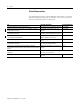
A-4 Specifications 1746-NT4 Module Accuracy Input Type Without Autocalibration(1) With Autocalibration(1) Maximum Error Maximum Error Temperature Drift @ 25°C @ 77°F (0°C-60°C) J ±1.06°C ±1.91°F ±0.0193°C/°C, °F/°F K ±1.72°C ±3.10°F ±0.0328°C/°C, °F/°F T ±1.43°C ±2.57°F ±0.0202°C/°C, °F/°F E ±0.72°C ±1.3°F ±0.0190°C/°C, °F/°F S ±3.61°C ±6.5°F ±0.0530°C/°C, °F/°F R ±3.59°C ±6.46°F ±0.0530°C/°C, °F/°F B ±3.12°C ±5.62°F ±0.0457°C/°C, °F/°F N ±1.39°C ±2.5°F ±0.
Specifications ( ˚ C) ( ˚ F) 50/60 Hz 0.40 0.72 10 Hz 0.20 0.36 2.40 4.32 0.30 0.54 0.15 0.27 1.60 2.88 0.20 0.36 0.10 0.18 0.80 1.44 0.10 0.18 0.05 0.09 Resolution 250 Hz 3.20 5.76 Type J Thermocouple 0.00 _300 _508 _150 _238 0 32 150 302 Temperature ( ˚ C) (˚ F) Resolution 250 Hz 50/60 Hz A-5 300 572 ( ˚ C) (˚ F) 450 842 600 111 2 750 1382 900 1652 Type K Thermocouple 12.80 23.04 1.60 2.88 10 Hz 0.8 1.44 9.60 17.28 1.20 2.16 0.6 1.08 6.40 11.52 0.80 1.44 0.4 0.72 3.
A-6 Specifications Resolution 250 Hz (˚ C) (˚ F) 50/60 Hz Type N Thermocouple 10 Hz 1.60 2.88 0.20 0.36 0.10 0.18 1.28 2.30 0.16 0.29 0.08 0.14 0.96 1.73 0.12 0.22 0.06 0.1 1 0.64 1.15 0.08 0.14 0.04 0.07 0.04 0.07 0.02 0.04 0.32 0.58 0.00 Resolution 250 Hz _300 _508 _150 _ 238 0 32 150 302 300 572 450 842 600 750 1112 1382 (˚ C) Temperature (˚ F) 900 1652 1050 1922 1200 2192 1350 2462 1500 2732 ( ˚ C) ( ˚ F) 50/60 Hz 10 Hz 6.79 12.22 1.20 2.16 0.6 1.08 4.53 8.15 0.
Specifications (˚ C) ( ˚ F) 50/60 Hz 10 Hz 6.79 12.22 1.20 2.16 0.6 1.08 4.53 8.15 0.80 1.44 0.4 0.72 2.26 4.07 0.40 0.72 0.2 0.36 Resolution 250 Hz 0.0 ( ˚ C) (˚ F) Resolution A-7 Type S Thermocouple _300 _508 _150 _238 0 32 150 302 300 572 450 842 600 750 900 1112 1382 1652 (˚ C) Temperature ( ˚ F) 1050 1200 1350 1500 1650 1800 1922 2192 2462 2732 3002 3272 Type T Thermocouple 250 Hz 50/60 Hz 10 Hz 9.05 16.29 1.60 2.88 0.8 1.44 6.79 12.22 1.20 2.16 0.6 1.08 4.53 8.
A-8 Specifications ( ˚ C) (˚ F) Resolution 250 Hz Type B Thermocouple 50/60 Hz 10 Hz 3.20 5.76 0.80 1.44 0.4 0.72 2.40 4.32 0.60 1.08 0.3 0.54 1.60 2.88 0.40 0.72 0.2 0.36 0.80 1.44 0.20 0.36 0.1 0.18 0.
Appendix B NT4 Configuration Worksheet The following configuration procedure and worksheet are provided to help you configure each of the channels on your thermocouple module. Channel Configuration Procedure The channel configuration word consists of bit fields, the settings of which determine how the channel will operate. This procedure looks at each bit field separately and helps you configure a channel for operation.
B-2 NT4 Configuration Worksheet 3. Determine the desired state for the channel data word if an open circuit condition is detected for that channel. Enter the 2-digit binary code in bit field 6-7 of the channel configuration word. Bits 6 and 7 Open Circuit Select 00 = zero 01 = upscale 10 = downscale 4.
NT4 Configuration Worksheet B-3 9. Enter the completed configuration words for each module into the summary worksheet on the following page. 10. Following the steps outlined in chapter 2 or in chapter 6, enter this configuration data into your ladder program and copy it to the thermocouple module.
B-4 NT4 Configuration Worksheet Channel Configuration Worksheet 11 10 9 8 7 6 5 4 3 2 1 0 Bit Number 15 14 13 12 0 0 0 0 Channel 0 0 0 0 0 Channel 1 0 0 0 0 Channel 2 0 0 0 0 Channel 3 Input Type Select Data Format Select Open Circuit Select Temperature Units Select Filter Frequency Select Channel Enable Not Used Bit Definitions: Description Specification Bits 0-3 Input Type Select 0000 = J 0001 = K 0010 = T 0011 = E Bits 4 and 5 Data Format Select 00 = engineer
Appendix C Thermocouple Restrictions Following are some restrictions extracted from NBS Monograph 125 (IPTS-68) issued March 1974 on thermocouples J, K, T, E, R, and S. J Type Thermocouple (Iron vs. Copper-Nickel ) The J thermocouple “is the least suitable for accurate thermometry because there are significant nonlinear deviations in the thermoelectric output from different manufacturers. ...
C-2 Thermocouple Restrictions “ASTM Standard E230-72 in the Annual Book of ASTM Standards [1972] specifies that the standard limits of error for Type J commercial thermocouples be ±2.2C between 0 and 277C and ±3/4 percent between 277 and 760C. Limits of error are not specified for Type J thermocouples below 0C or above 760C. Type J thermocouples can also be supplied to meet special limits of error, which are equal to one half the limits given above.
Thermocouple Restrictions C-3 “They should not be used in sulfurous, reducing, or alternately reducing and oxidizing atmospheres unless suitably protected with protecting tubes. They should not be used in vacuum (at high temperatures) for extended times because the Chromium in the positive thermoelement vaporizes out of solution and alters the calibration. They should also no be used in atmospheres that promote “green-rot” corrosion (those with low, but not negligible, oxygen content).
C-4 Thermocouple Restrictions “Type T thermoelements are not well suited for use in nuclear environments, since both thermoelements are subject to significant changes in composition under thermal neutron irradiation. The copper in the thermoelement is converted to nickel and zinc.” “Because of the high thermal conductivity of Type TP thermoelements, special care should be exercised in the use of the thermocouples to insure that both the measuring and reference junctions assume the desired temperatures.
Thermocouple Restrictions C-5 “The negative thermoelement, a copper-nickel alloy, is subject to composition changes under thermal neutron irradiation since the copper is converted to nickel and zinc.” “ASTM Standard E230-72 in the Annual Book of ASTM Standards [1972] specifies that the standard limits of error for the Type E commercial thermocouples be ±1.7C between 0 and 316C and ±1/2 percent between 316 and 871C. Limits of error are not specified for Type E thermocouples below 0C.
C-6 Thermocouple Restrictions “ASTM Standard E230-72 in the Annual Book of ASTM Standards [1972] specifies that the standard limits of error for Type S {and R} commercial thermocouples be ±1.4C between 0 and 538C and ±1/4 percent between 538 and 1482C. Limits of error are not specified for Type S {or R} thermocouples below 0C. The recommended upper temperature limit for continuous use of protected thermocouples, 1482C, applies to AWG 24 (0.5 mm) wire.
Appendix D Thermocouple Types This appendix describes the three types of thermocouple junctions. They are • Grounded Junction - The measuring junction is physically connected to the protective metal sheath providing electrical continuity between junction and sheath. • Ungrounded Junction – The measuring junction is electrically isolated from the protective metal sheath. (Also called Insulated Junction.) • Exposed Junction – Does not have a protective metal sheath so the measuring junction is exposed.
D-2 Thermocouple Types Publication 1746-UM007C-EN-P - July 2004
Appendix E Configuring the 1746-NT4 Module with RSLogix 500 This appendix describes how to configure the NT4 module with RSLogix 500 v6.10 or higher. To configure your module: 1. Access the I/O Configuration menu. 2. Determine the chassis number and slot location of where the NT4 module is located. Highlight the module.
E-2 Configuring the 1746-NT4 Module with RSLogix 500 3. Press the Adv Config button. The following dialog box appears. 4. Press the Configure button. This allows you to configure options for each channel. The following dialog box appears.
Configuring the 1746-NT4 Module with RSLogix 500 E-3 The dialog box allows you to access the parameters for all channels. Each tab has an identical menu with the parameters shown. The following list provides the options for a parameter. Parameter Description Channel Enabled Controls bit 11 of the configuration file and sets whether the channel is being used. Input Type Sets bits 0-3 and sets the type of thermocouple being used.
E-4 Configuring the 1746-NT4 Module with RSLogix 500 5. Press OK to set the parameters. The following dialog box appears. 6. Choose the data file for the configuration and the location for the configuration rung within your ladder logic program. 7. Press OK. The following rung is added to the ladder logic program. This rung will send the configuration to the module on the first program scan.
Glossary The following terms and abbreviations are used throughout this manual. For definitions of terms not listed here refer to Allen-Bradley’s Industrial Automation Glossary, Publication AG-7.1. A/D - Refers to the analog to digital converter inherent to the NT4 thermocouple input module. The converter produces a digital value whose magnitude is proportional to the instantaneous magnitude of an analog input signal. attenuation - The reduction in the magnitude of a signal as it passes through a system.
Glossary 2 data word - A 16-bit integer that represents the value of the analog input channel. The channel data word is valid only when the channel is enabled and there are no channel errors. When the channel is disabled the channel data word is cleared (0). digital filter - A low-pass noise filter incorporated into the A/D converter. The digital filter provides a very steep roll-off above its cut-off frequency, which provides high frequency noise rejection.
Glossary 3 remote configuration - A control system where the chassis can be located several thousand feet from the processor chassis. Chassis communication is via the 1747-SN Scanner and 1747-ASB Remote I/O Adapter. resolution - The smallest detectable change in a measurement, typically expressed in engineering units (e.g. 0.15C) or as a number of bits. For example a 12-bit system has 4,096 possible output states. It can therefore measure 1 part in 4096.
Glossary 4 Notes: Publication 1746-UM007C-EN-P - July 2004
Index A A/D definition G-1 addressing configuration word 4-2 data word 4-3 status word 4-3 alarms 6-6 application example basic 8-1 supplementary 8-4 attenuation definition G-1 B bit allocation 5-1 C cable tie slots 1-3 channel definition G-1 channel configuration error 7-4 fault detection bit 5-17 procedure 5-2, B-1 Channel Data Word 5-12 channel status bit 5-16 Channel Status Checking 5-13 chassis definition G-1 CJC 3-12 definition G-1 CMRR definition G-1 cold junction compensation 3-12 definition G-1 c
2 Index using multiple thermocouples D-1 extension wire 1-5 F filter frequency definition G-2 examining in status word 5-16 setting in configuration word 5-11 FSR definition G-2 full scale error definition G-2 full scale range definition G-2 G gain drift definition G-2 gain error definition G-2 gain error See full scale error getting started tools required 2-1 grounded thermocouples using multiple thermocouples D-1 H heat considerations 3-5 I ID code 4-1 input channel multiplexing 1-5 input data scali
Index overview 5-17 P PID input type 5-5 instruction 6-5 pinout diagram 3-7 power-up sequence 1-4 programming alarms 6-6, 6-7 configuration settings making changes 6-3 dynamic 6-3 PID instruction 6-5 verifying channel configuration changes 6-4 proportional counts input 5-5 publications, related P-2 Q quick start for experienced users 2-1 R reconfiguration time 4-9 related publications P-2 remote configuration definition G-3 removable terminal block 1-3 resolution definition G-3 effective 4-4 S samplin
4 Index overview 5-16 update time definition G-3 V Verification of dynamic configuration change 6-4 Publication 1746-UM007C-EN-P - July 2004 W wiring 3-1 routing considerations 3-5 terminal wiring cold junction compensation 3-12 shield connections 3-10 worksheets B-1
Index 5 Publication 1746-UM007C-EN-P - July 2004
Rockwell Automation Support Rockwell Automation provides technical information on the web to assist you in using our products. At http://support.rockwellautomation.com, you can find technical manuals, a knowledge base of FAQs, technical and application notes, sample code and links to software service packs, and a MySupport feature that you can customize to make the best use of these tools.