
User Manual


Publication 1746-UM003A-EN-P
Module Diagnostics and Troubleshooting 6-3
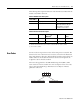
The following tables explain the function of the channel status LEDs while the
module status LED is turned on.
Table 6.1 Module Status Description
Table 6.2 Channel Status Description
Error Codes
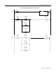
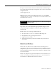
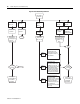
I/O error codes are reported in word S:6 of the SLC processor status file. The
format for the error codes in the status word (S:6) is shown in the illustration
below. The characters denoted as XX in the illustration below represent the slot
number (Hex) for the module. The characters denoted as YY represent the
2-digit hex code for the fault condition.
The error codes applicable to the RTD Module range from 50H to 5AH.
Some of these are non-recoverable errors. For a description of the error codes,
refer to SLC 500 and MicroLogix 1000 Instruction Set Reference Manual,
publication 1747-6.15.
If Module
Status LED is:
Indicated Condition: Corrective Action:
ON Proper Operation No action required.
Off or Flashing Module Fault Cycle power. If condition persists,
replace the module or call your
local distributor or Rockwell
Automation for assistance.
LED
Power-up
(1)
(1) Module is disabled during powerup.
Module Operation
(No Error)
(2)
(2) Channel status LED is On if the respective channel is enabled and Off if the channel is disabled.
Module Error Channel
Error
Ch 0-7 Status On On/Off
Off
(3)
(3) Error if channel is enabled.
Flashes
Mod. Status Off On Flashes/Off On
YY - Error Code (Hex)
XXYY
XX - Chassis Slot Number (Hex)