
User Manual

Publication 1746-UM003A-EN-P
Ladder Programming Examples 5-3
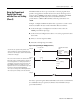
This example transfers configuration data and sets the channel enable bits of all
eight channels with a single file copy instruction. The file copy instruction
copies 8 data words from an integer file you create in the SLC’s memory, to the
RTD module’s channel configuration words. This procedure is described
below.
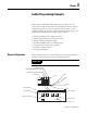
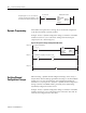
Figure 5.3 Copy File Data Flow
Procedure
1.
1.1.
1. Using the memory map function to create a data file, create integer file
N10. Integer file N10 should contain eight elements (N10:0 through
N10:7).
2.
2.2.
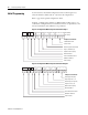
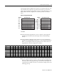
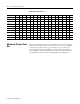
2. Using the RSLogix 500 data monitor function, enter the configuration
parameters for all eight RTD channels into a source integer data file N10.
Refer to the Configuration Word Setup illustration for the bit values. See
Appendix B for a channel configuration worksheet.
3.
3.3.
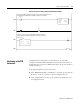
3. Use the copy file instruction (COP) to copy the contents of integer file
N10 to the eight consecutive output words of the RTD module beginning
with O:3.0. To do this, program a rung as shown below. All elements are
copied from the specified source file to the destination during the first scan
following power up.
Source Data File Destination Data File
Channel Configuration Word 0
Channel Configuration Word 1
Channel Configuration Word 2
Channel Configuration Word 3
Channel Output Word 0
Channel Output Word 1
Channel Output Word 2
Channel Output Word 3
O:3.0
O:3.1
O:3.2
O:3.3
NI0:0
NI0:1
NI0:2
NI0:3
Address Address
Channel Configuration Word 4
Channel Configuration Word 5
Channel Configuration Word 6
Channel Configuration Word 7
Channel Output Word 4
Channel Output Word 5
Channel Output Word 6
Channel Output Word 7
NI0:4
NI0:5
NI0:6
NI0:7
O:3.4
O:3.5
O:3.6
O:3.7
Bit 1514131211109876543210
N10:0 1011101100100000
N10:1 1011101100100000
N10:2 1011101100100000
N10:3 1011101100100000
N10:4 0101110001011000
N10:5 0101110001011000
N10:6 0101110001011000
N10:7 0101110001011000