
User Manual

Publication 1746-UM003A-EN-P
5-2 Ladder Programming Examples
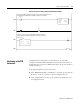
Initial Programming
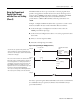
To enter data into the channel configuration word (O:e.0 through O:e.7)
when the channel is disabled (bit 11 = 0), follow the example below.
Refer to page 4-5 for specific configuration details.
Example - Configure eight channels of a RTD module residing in slot 3 of a
1746 chassis. Configure the first four channels with one set of parameters, and
the last four channels with a different set of parameters.
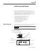
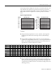
Figure 5.1 Configuration Word Setup for Channels 0 through 3
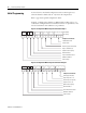
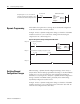
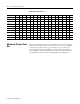
Figure 5.2 Configuration Word Setup for Channels 4 Through 7
11121415 13
10
910 8
1
67
00
45
000
0123
111 0
1
0
1
0
Bit Number
Bit Setting
Configures Channel For:
100
Ω Platinum RTD
Scaled-for-PID
Broken Input (Zero Data Word)
Degrees Fahrenheit (°F)
50/60 Hz Filter Frequency
Channel Enabled
0.25 mA Excitation Current
Calibration Enabled
Lead R Always
11121415 13
11
910 8
0
67
01
45
100
0123
001 1
0
1
0
0
Configures Channel For:
10
Ω Copper RTD (426)
Engineering Units x 10
Broken Input (Set Upscale)
Degrees Celsius (°C)
800 Hz Filter Frequency
Channel Enabled
0.25 mA Excitation Current
Calibration Disabled
Lead R Periodic