
User Manual

1 Publication 1746-UM003A-EN-P
Chapter
5
Ladder Programming Examples
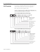
Earlier chapters explained how the configuration word defines the way a
channel operates. This chapter shows the programming required to enter the
configuration word into the processor memory. It also provides you with
segments of ladder logic specific to unique situations that might apply to your
programming requirements. The example segments include:
• initial programming of the configuration word
• dynamic programming of the configuration word
• verifying channel configuration changes
• interfacing the RTD module to a PID instruction
• using proportional counts scaling (example)
• monitoring channel status bits
• invoking autocalibration
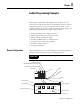
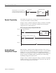
Device Configuration
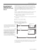
The following illustration is used for clarification of the ensuing ladder logic
examples and is not intended to represent an RTD application.
IMPORTANT
Chapter 7 shows a typical application for the RTD module.
1230
F8
˚
C
°
F
Push-button Switch I:1/1
Pilot Light O:2/0
Pilot Light O:2/1
SLC Processor
1746-IB8 DC Input Module (Sinking)
1746-OB8 DC Output Module (Sourcing)
1746-NR8 RTD Module
Slot #
RTD 0
RTD 1
RTD 2
RTD 3
Pilot Light O:2/3
Pilot Light O:2/2
Selector Switch I:1/0
Display Panel
Ch 0 Alarm Ch 1 Alarm Ch 2 Alarm Ch 3 Alarm
Autocalibration