
User Manual

Publication 1746-UM003A-EN-P
4-20 Channel Configuration, Data, and Status
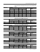
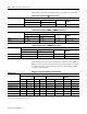
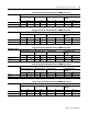
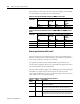
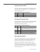
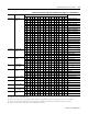
Figure 4.7 Module Input Image (Status Word)
The channel status word can be analyzed bit by bit. Each bit’s status (0 or 1)
tells you how the input data from the RTD sensor or resistance device
connected to a specific channel is translated for your application. The bit status
also informs you of any error condition and can tell you what type error
occurred.
A bit-by-bit examination of the status word is provided in the following table.
Channel 0 Status Word
Channel 1 Status Word
Channel 2 Status Word
Channel 3 Status Word
Channel 4 Status Word
Channel 5 Status Word
Channel 6 Status Word
Channel 7 Status Word
I:e.8
I:e.9
I:e.10
I:e.11
I:e.12
I:e.13
I:e.14
I:e.15