
User Manual

Publication 1746-UM003A-EN-P
Channel Configuration, Data, and Status 4-5
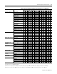
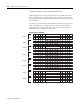
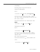
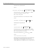
Table 4.1 Channel Configuration Word (O:e.0 through O:e.7) - Bit Definitions
Define To Select Make these bit settings in the Channel Configuration Word
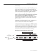
1514131211109876543210
Input type selection 100 Pt (385)
0000
200 Pt (385)
0001
500 Pt (385)
0010
1000 Pt (385)
0011
100 Pt (3916)
0100
200 Pt (3916)
0101
500 Pt (3916)
0110
1000 Pt (3916)
0111
10 Cu (426)
(1)
1000
120 Ni (618)
(2)
1001
120 Ni (672)
1010
604 NiFe (518)
1011
150
Ω Resistance Input 1100
500
Ω Resistance Input 1101
1000
Ω Resistance Input 1110
3000
Ω Resistance Input 1111
Data format selection
Engineering units x 1
(3)
00
Engineering units x 10
(4)
01
Scaled-for-PID 10
proportional counts 11
Broken input selection Set to Zero 00
Set to Upscale 01
Set to Downscale 10
Invalid 11
Temperature units
selection
Degrees C
(5)
0
Degrees F
(5)
1
Filter frequency selection 28 Hz 00
50/60 Hz 01
800 Hz 10
6400 Hz 11
Channel enable Channel Disabled 0
Channel Enabled 1
Excitation current
selection
1.0 mA 0
0.25 mA 1
Cal. Disable Enable 0
Disable 1
Lead R. Enable Disable 0 0
Periodic 0 1
Always 1 0
Invalid 1 1
(1) Actual value at 0 °C is 9.042Ω per SAMA standard RC21-4-1966.
(2) Actual value at 0 °C is 100
Ω per DIN standard.
(3) Values are in 0.1 degree /step or 0.1
Ω/step for all resistance input types, except 150Ω. For the 150Ω resistance input type, the values are in 0.01Ω/step.
(4) Values are in 1 degree /step or 1
Ω/step for all resistance input types, except 150Ω. For the 150Ω resistance input type, the values are in 0.1Ω/step.