
User Manual

Publication 1746-UM003A-EN-P
Overview 1-9
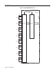
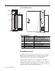
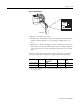
Figure 1.4 LED Indicators
The purpose of the LEDs is as follows:
• Channel Status - One LED for each of the 8 input channels indicates if the
channel is enabled, disabled, or is not operating as configured, due to an
error.
• Module Status - If OFF or flashing at any time, other than at powerup, this
LED indicates that non-recoverable module errors (for example, diagnostic
or operating errors) have occurred. The LED is ON if there are no module
errors.
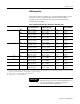
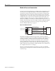
The status of each LED, during each of the operational states (for example,
powerup, module operation and error), is depicted in the following table.
LED
Power-up
(1)
(1) Module is disabled during powerup.
Module Operation
(No Error)
(2)
(2) Channel status LED is On if the respective channel is enabled and Off if the channel is disabled.
Module Error Channel
Error
Ch 0 to 7 Status On On/Off
Off
(3)
(3) Error if channel is enabled.
Flashes
Mod. Status Off On Flashes/Off On
RTD Module