
User Manual

Publication 1746-UM003A-EN-P
1-6 Overview
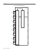
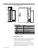
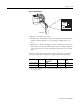
Figure 1.2 RTD Module Hardware
Table 1.4 Hardware Features
General Diagnostic Features
The RTD module contains diagnostic features that can be used to help you
identify the source of problems that may occur during power up or during
normal channel operation. These power-up and channel diagnostics are
explained in Chapter 6, Module Diagnostics and Troubleshooting.
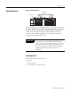
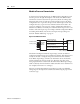
The RTD module communicates to the SLC 500 processor through the
parallel backplane interface and receives +5V dc and +24V dc power from the
SLC 500 power supply through the backplane. No external power supply is
required. You may install as many RTD modules in your system as the power
supply can support, as shown in the illustration below.
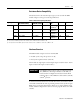
INPUT SIGNAL RANGES
RTD TYPES:
PLATINUM, COPPER
NICKEL, NICKEL - IRON
RESISTANCE (OHMS):
150, 500, 1000, 3000
MADE IN U.S.A
SC P/N: 9060018-01
SC S/N: 167076
SC MFD: 0020
BACKPLANE REQUIREMENTS:
55mA @ 24VDC, 100mA @ 5VDC
RTD / resistance INPUT MODULE
SLC 500
1746-NR8 A 1.00
FRNSERCAT
WIN (21) 1G0AA2ZT
(21) 1G0AA2ZT
LISTED
1P00
IND CONT EQ.
FOR HAZ LOC
CL I, DIV2 GP ABCD
C
U
L
®
U
L
®
6
7
5
1
2
3
4
RTD 0
Sense 0
Return 0
RTD 1
Sense 1
Return 1
RTD 2
Sense 2
Return 2
RTD 3
Sense 3
Return 3
RTD 4
Sense 4
Return 4
RTD 5
Sense 5
Return 5
RTD 6
Sense 6
Return 6
RTD 7
Sense 7
Return 7
1746-NR8
Item Description Function
1 Channel Status LED
Indicators (green)
Displays operating and fault status of
channels 0, 1, 2, 3, 4, 5, 6, and 7
2 Module Status LED (green) Displays module operating and fault status
3 Removable Terminal Block Provides physical connection to input devices
(Catalog # 1746-RT35)
4 Cable Tie Slots Secures wiring from module
5 Door Label Provides terminal identification
6 Side Label (Nameplate) Provides module information
7 Self-Locking Tabs Secures module in chassis slot