
User Manual

Publication 1746-UM003A-EN-P
Overview 1-5
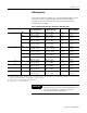
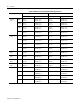
Resistance Device Compatibility
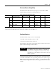
The table below lists the resistance input types you can use with the RTD
module and gives each type’s associated specifications.
Table 1.3 Resistance Input Specifications
Hardware Overview
The RTD module occupies one slot in an SLC 500:
• modular system, except the processor slot (0)
• fixed system expansion chassis (1746-A2)
The module uses eight input words and eight output words for Class 1 and 16
input words and 24 output words for Class 3.
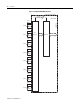
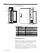
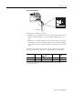
As shown in the illustration below and table that follows, the module contains
a removable terminal block (item 3) providing connection for any mix of eight
RTD sensors or resistance input devices. There are no output channels on the
module. Module configuration is done via the user program. There are no DIP
switches.
Input Type Resistance Range
(0.25 mA Excitation)
Resistance Range
(1.0 mA Excitation)
Accuracy
(1)
Temperature
Drift
Resolution Repeatability
Resistance 150
Ω 0Ω to 150Ω 0Ω to 150Ω
(2)
±0.004Ω/°C
(±0.002
Ω/°F)
(3)
0.01Ω 0.04Ω
500Ω 0Ω to 500Ω 0Ω to 500Ω 0.5Ω ± 0.012Ω/°C
(± 0.007
Ω/°F)
0.1
Ω 0.2Ω
1000Ω 0Ω to 1000Ω 0Ω to 1000Ω 1.0Ω 0.025Ω/ C
(
0.014Ω/ F)
0.1
Ω 0.2Ω
3000Ω 0Ω to 3000Ω 0Ω to 1200Ω
1.5Ω
0.040Ω/ C
(
0.023Ω/ F)
0.1
Ω 0.2Ω
(1) The accuracy values assume that the module was calibrated within the specified temperature range of 0°C to 60°C (32°F to 140°F).
(2) The accuracy for 150
Ω is dependent on the excitation current: 0.2Ω at 0.25 mA and 0.15Ω at 1.0 mA
(3) The temperature drift for 150
Ω is dependent on the excitation current: 0.006Ω/°C at 0.25 mA and 0.004Ω at 1.0 mA
IMPORTANT
If the RTD module resides in a remote configuration with a
SLC 500 Remote I/O Adapter Module (1747-ASB), use
block transfer for configuration and data retrieval. Block
transfer requires a 1747-SN Remote I/O Scanner (Series B)
or PLC
®
processor.