
User Manual


1 Publication 1746-UM003A-EN-P
Appendix
B
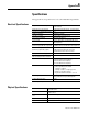
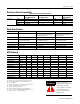
Configuration Worksheet for RTD/Resistance
Module
See Chapter 4 for worksheet procedure.
11121415 13 910 8 6745 2 1 03
Bit Number
Channel 0
Channel 1
Channel 2
Channel 3
Input Type Select
Data Format Select
Broken Input Select
Temperature Units Select
Filter Frequency Select
Channel Enable
Excitation Current Select
Calibration Disable
Lead R Enable
Channel 4
Channel 5
Channel 6
Channel 7
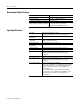
Bit Definitions:
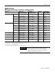
Bits 0 through 3 Input Type Select 0000 = 100
Ω Pt. (385)
0001 = 200
Ω Pt. (385)
0010 = 500
Ω Pt. (385)
0011 = 1000
Ω Pt. (385)
0100 = 100
Ω Pt. (3916)
0101 = 200
Ω Pt. (3916)
0110 = 500
Ω Pt. (3916)
0111 = 1000
Ω Pt. (3916)
1000 = 10
Ω Cu (426)
(1)
1001 = 120Ω Ni (618)
(2)
1010 = 120Ω Ni (672)
1011 = 604
Ω Ni-Fe (518)
1100 = 150
Ω Potentiometer
1101= 500
Ω Potentiometer
1110= 1000
Ω Potentiometer
1111= 3000
Ω Potentiometer
Bits 4 and 5 Data Format Select
00 = engineering units, x1
(3)
01 = engineering units, x10
(4)
10 = scaled-for-PID (0 to 16383)
11 = proportional counts (-32768 to +32767)
Bits 6 and 7 Broken Input Select 00 = zero 01 = upscale 10 = downscale 11 = lnvalid
Bit 8 Temperature Units
Select
0 = degrees Celsius 1 = degrees Fahrenheit
Bits 9 and 10 Filter Frequency Select 00 = 28 Hz 01 = 50/60 Hz 10 = 800 Hz 11 = 6400 Hz
Bit 11 Channel Enable 0 = channel disabled 1 = channel enabled
Bit 12 Excitation Current
Select
0 = 1.0 mA 1 = 0.25 mA
Bit 13 Cal. Disable 0 = enable calibration
(default)
1 = disable calibration
Bits 14 and 15 Lead R Enable 00 = Disable, 01 = Periodic, 10 = Always, 11 = Invalid
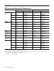
(1) Actual value at °C is 9.042Ω per SAMA standard RC21-4-1966.
(2) Actual value at 0°C is 100Ω per DIN standard.
(3) Values are in 0.1° /step or 0.1 Ω/step for all resistance input types, except 150Ω. For the 150Ω resistance input type, the values are in 0.01Ω/step.
(4) Values are in 1° /step or 1Ω /step for all resistance input types, except 150Ω. For the 150Ω resistance input type, the values are in 0.1Ω/step.