SLC 500™ RTD/Resistance Input Module (Catalog Number 1746-NR8) User Manual
Important User Information Because of the variety of uses for the products described in this publication, those responsible for the application and use of this control equipment must satisfy themselves that all necessary steps have been taken to assure that each application and use meets all performance and safety requirements, including any applicable laws, regulations, codes and standards.
Table of Contents Preface Who Should Use This Manual . . . . . . . . . . . . . . . . . . . . . . . . . . . . Purpose of This Manual . . . . . . . . . . . . . . . . . . . . . . . . . . . . . . . . . Related Documentation . . . . . . . . . . . . . . . . . . . . . . . . . . . . . . Common Techniques Used in this Manual . . . . . . . . . . . . . . . . . . . Rockwell Automation Support . . . . . . . . . . . . . . . . . . . . . . . . . . . . Local Product Support . . . . . . . . . . . . . . . . . . . . . . . . .
Table of Contents ii Chapter 3 Preliminary Operating Considerations Module ID Code. . . . . . . . . . . . . . . . . . . . . . . . . . . . . . . . . . . . . . . 3-1 Module Addressing . . . . . . . . . . . . . . . . . . . . . . . . . . . . . . . . . . . . . 3-2 Output Image - Configuration Words. . . . . . . . . . . . . . . . . . . . 3-4 Input Image - Data Words and Status Words . . . . . . . . . . . . . . 3-4 Channel Filter Frequency Selection . . . . . . . . . . . . . . . . . . . . . . . . .
Table of Contents iii Chapter 5 Ladder Programming Examples Device Configuration . . . . . . . . . . . . . . . . . . . . . . . . . . . . . . . . . . . 5-1 Initial Programming . . . . . . . . . . . . . . . . . . . . . . . . . . . . . . . . . . . . 5-2 Dynamic Programming. . . . . . . . . . . . . . . . . . . . . . . . . . . . . . . . . . 5-4 Verifying Channel Configuration Changes . . . . . . . . . . . . . . . . . . . 5-4 Interfacing to the PID Instruction . . . . . . . . . . . . . . . . . . . . . . . . .
Table of Contents iv Appendix B Configuration Worksheet for RTD/ Resistance Module Glossary Index Publication 1746-UM003A-EN-P
Preface Read this preface to familiarize yourself with the rest of the manual. This preface covers the following topics: • • • • • Who Should Use This Manual who should use this manual the purpose of this manual terms and abbreviations conventions used in this manual Allen-Bradley support Use this manual if you are responsible for designing, installing, programming, or troubleshooting control systems that use Allen-Bradley small logic controllers.
Preface 2 Related Documentation The following documents contain information that may be helpful to you as you use Allen-Bradley SLC™ products.To obtain a copy of any of the Allen-Bradley documents listed, contact your local Allen-Bradley office or distributor.
Preface Common Techniques Used in this Manual The following conventions are used throughout this manual: Rockwell Automation Support Rockwell Automation offers support services worldwide, with over 75 Sales/ Support Offices, 512 authorized Distributors and 260 authorized Systems Integrators located throughout the United States alone, plus Rockwell Automation representatives in every major country in the world. 3 • Bulleted lists such as this one provide information, not procedural steps.
Preface 4 Publication 1746-UM003A-EN-P
Chapter 1 Overview This chapter describes the 8-channel 1746-NR8 RTD/Resistance Input Module and explains how the SLC controller gathers RTD (Resistance Temperature Detector) temperature or resistance-initiated analog input from the module. Included is: • a general description of the module’s hardware and software features • an overview of system operation For the rest of the manual, the 1746-NR8 RTD/Resistance Input Module is referred to as simply the RTD module.
1-2 Overview Figure 1.1 Simplified RTD Module Circuit Constant Current Source Ic=0.25 or 1.
Overview 1-3 RTD Compatibility The following table lists the RTD types used with the RTD module and gives each type’s associated temperature range, resolution, and repeatability specifications. The next table shows the accuracy and temperature drift specifications for the RTDs. Input Type Platinum (385)(2) 100Ω 200Ω 500Ω 1000Ω Platinum (3916)(2) 100Ω 200Ω 500Ω 1000Ω Copper (426)(2) (3) 10Ω Nickel (618)(2) (4) 120Ω Nickel (672)(2) 120Ω Nickel Iron (518)(2) 604Ω Table 1.
1-4 Overview Table 1.2 RTD Accuracy and Temperature Drift Specifications Input Type 0.25 mA Excitation 1.0 mA Excitation Accuracy Temperature Drift Accuracy Temperature Drift 100Ω ±0.5°C (±0.9°F) ±0.012°C/°C (±0.012°F/°F) ±0.7°C (±1.3°F) ±0.020°C/°C (±0.020°F/°F) 200Ω ±0.6°C (±1.1°F) ±0.015°C/°C (± 0.015°F/°F) ±0.7°C (±1.3°F) ±0.020°C/°C (±0.020°F/°F) 500Ω ±0.7°C (±1.3°F) ±0.020°C/°C (±0.020°F/°F) ±0.5°C (± 0.9°F) ±0.012°C/°C (±0.012°F/°F) 1000Ω ±1.2°C (±2.2°F) ±0.035°C/°C (±0.
Overview 1-5 Resistance Device Compatibility The table below lists the resistance input types you can use with the RTD module and gives each type’s associated specifications. Input Type Resistance 150Ω Resistance Range (0.25 mA Excitation) 0Ω to 150Ω 500Ω 0Ω to 500Ω 1000Ω 0Ω to 1000Ω 3000Ω 0Ω to 3000Ω Table 1.3 Resistance Input Specifications Resistance Range Accuracy(1) Temperature (1.0 mA Excitation) Drift (2) 0Ω to 150Ω ±0.004Ω/°C (±0.002Ω/°F) (3) 0Ω to 500Ω 0.5Ω ± 0.012Ω/°C (± 0.
1-6 Overview Figure 1.2 RTD Module Hardware 6 INPUT 1 CHANNEL ST ATUS CAT SER FRN RTD / resistance INPUT MODULE SLC 500 1.00 ® UL LISTED 1P00 IND CONT EQ. FOR HAZ LOC CL I, DIV2 GP ABCD C U ®L 150 SC P/N: 9060018-01 SC S/N: 167076 SC MFD: 0020 MADE IN U.S.
Overview System Overview 1-7 Figure 1.3 RTD Configuration RTD Modules SLC Processor Each individual channel on the RTD module can receive input signals from 2, 3 or 4-wire RTD sensors or from resistance input devices. You configure each channel to accept either input. When configured for RTD input types, the module converts the RTD readings into linearized, digital temperature readings in °C or °F. When configured for resistance inputs, the module provides a linear resistance value in ohms.
1-8 Overview Power-up At power-up, the RTD module checks its internal circuits, memory, and basic functions via hardware and software diagnostics. During this time, the module status LED remains off, and the channel status LEDs are turned on. If no faults are found during the power-up diagnostics, the module status LED is turned on, and the channel status LEDs are turned off.
Overview 1-9 Figure 1.4 LED Indicators INPUT CHANNEL ST ATUS 0 1 2 3 MODULE RTD / resistance 4 5 6 7 RTD Module The purpose of the LEDs is as follows: • Channel Status - One LED for each of the 8 input channels indicates if the channel is enabled, disabled, or is not operating as configured, due to an error. • Module Status - If OFF or flashing at any time, other than at powerup, this LED indicates that non-recoverable module errors (for example, diagnostic or operating errors) have occurred.
1-10 Overview Module to Processor Communication As shown in the following illustration, the RTD module communicates with the SLC processor through the backplane of the chassis. The RTD module transfers data to/receives data from the processor by means of an image table. The image table consists of eight input words and eight output words when configured for Class 1 operation; 16 input words and 24 output words when configured for Class 3 operation.
Chapter 2 Installation and Wiring This chapter tells you how to: • • • • • • comply to European union directives avoid electrostatic damage determine the RTD module’s chassis power requirement choose a location for the RTD module in the SLC chassis install the RTD module wire the RTD module’s terminal block This product is approved for installation within the European Union and EEA regions. It has been designed and tested to meet the following directives.
2-2 Installation and Wiring Safety Considerations Electrostatic Damage Electrostatic discharge can damage semiconductor devices inside this module if you touch backplane connector pins or other sensitive areas. Guard against electrostatic damage by observing the precautions listed next. ATTENTION ! Electrostatic discharge can degrade performance or cause permanent damage. Handle the module as stated below. • Wear an approved wrist strap grounding device when handling the module.
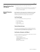
Installation and Wiring Power Requirements 2-3 The RTD module receives its power through the SLC500 chassis backplane from the fixed or modular +5V dc/+24V dc chassis power supply. The maximum current drawn by the module is shown in the table below. 5V dc 24V dc 0.100A 0.055A When you are using a modular system configuration, add the values shown in the table above to the requirements of all other modules in the SLC chassis to prevent overloading the chassis power supply.
2-4 Installation and Wiring Module Location in Chassis Modular Chassis Considerations Fixed Controller Compatibility Table IA4 IA8 IA16 IM4 IM8 IM16 OA8 OA16 OAP12 IB8 IB16 IB32 ITB16 IV8 IV16 IV32 ITV16 IC16 IG16 IH16 OB8 OB16 OB32 Series D or later OB16E OBP8 OBP16 OG16 OVP16 OV8 OV16 OV32 Series D or later IN16 OW4 OW8 OW16 OX8 IO4 IO8 IO12 NI4 NI8 NI16I NI16V NIO4I NIO4V FIO4I FIO4V NO4I NO4V NT4 NT8 INT4 NR4 HSCE HSCE2 BAS BASn KE KEn HS HSTP1 NR8 • • • • • • • • • • • • • • • • • • • • • • • • • •
Installation and Wiring 2-5 General Considerations Most applications require installation in an industrial enclosure to reduce the effects of electrical interference. RTD inputs are susceptible to electrical noises due to the small amplitudes of their signal. Group your modules to minimize adverse effects from radiated electrical noise and heat. Consider the following conditions when selecting a slot for the RTD module.
2-6 Installation and Wiring Removing the Terminal Block ATTENTION ! Never install, remove, or wire modules with power applied to the chassis or devices wired to the module. To avoid cracking the removable terminal block, alternate the removal of the slotted terminal block release screws. 1. Loosen the two terminal block release screws. Terminal Block Release Screw (Requires a 0.100 in slot screwdriver.) Maximum Torque = 0.25 Nm (2.25 in-lbs) 2.
Installation and Wiring 2-7 Installing the Module 1. Align the circuit board of the RTD module with the card guides located at the top and bottom of the chassis, as shown in the following illustration. Top and Bottom Module Releases Card Guide 2. Slide the module into the chassis until both top and bottom retaining clips are secured. Apply firm even pressure on the module to attach it to its backplane connector. Never force the module into the slot. 3.
2-8 Installation and Wiring Terminal Wiring ATTENTION ! Disconnect power to the SLC before attempting to install, remove, or wire the removable terminal wiring block. To avoid cracking the removable terminal block, alternate the removal of the terminal block release screws. Figure 2.
Installation and Wiring 2-9 For a 3-wire configuration, the module can compensate for a maximum cable length associated with an overall cable impedance of 25 ohms. IMPORTANT Details of cable specifications are shown on page A-5.
2-10 Installation and Wiring Figure 2.
Installation and Wiring IMPORTANT 2-11 To ensure temperature or resistance value accuracy, the resistance difference of the cable lead wires must be equal to or less than 0.01Ω.. There are several ways to insure that the lead values match as closely as possible. They are as follows: • Keep lead resistance as small as possible and less than 25 Ω. • Use quality cable that has a small tolerance impedance rating. • Use a heavy-gauge lead wire which has less resistance per foot.
2-12 Installation and Wiring Figure 2.3 2-Wire Potentiometer Connections to Terminal Block For details on wiring a potentiometer to the module, see page 2-8.
Installation and Wiring 2-13 Figure 2.4 3-Wire Potentiometer Connections to Terminal Block For details on wiring a potentiometer to the module, see page 2-8. Run RTD and sense wires from module to potentiometer and tie them to one point.
2-14 Installation and Wiring Wiring Input Devices to the Module To wire your 1746-NR8 module, follow these steps as shown in the illustration below: 1. At each end of the cable, strip some casing to expose the individual wires. 2. Trim the signal wires to 5.08-cm (2-inch) lengths. Strip about 4.76 mm (3/ 16 inch) of insulation away to expose the end of the wire. 3. At one end of the cable twist the drain wire and foil shield together, bend them away from the cable, and apply shrink wrap.
Installation and Wiring Calibration 2-15 The accuracy of a system that uses the RTD module is determined by the following: • the accuracy of the RTD • resistance mismatch of the cable wires that connect the RTD to the module • the accuracy of the RTD module For optimal performance at the customer site, the RTD module is calibrated at the factory prior to shipment. In addition, an autocalibration feature further ensures that the module performs to specification over the life of the product.
2-16 Installation and Wiring TIP To maintain system accuracy we recommend that you periodically perform an autocalibration cycle, for example: • whenever an event occurs that greatly changes the internal temperature of the control cabinet, such as opening or closing its door • at a convenient time when the system is not making product, such as during a shift change An autocalibration programming example is provided on page 5-10.
Chapter 3 Preliminary Operating Considerations This chapter explains how the RTD module and the SLC processor communicate through the module’s input and output image. It lists the preliminary setup and operation required before the RTD module can function in a 1746 I/O system.
3-2 Preliminary Operating Considerations Module Addressing The memory map shown in the following illustration displays how the output and input image tables are defined for the RTD module. Figure 3.1 Class 1 Memory Map Bit 15 Bit 0 Channel 4 Configuration Word Channel 5 Configuration Word Channel 6 Configuration Word Channel 7 Configuration Word Word 0 Word 1 Word 2 Word 3 Word 4 Word 5 Word 6 Word 7 Address O:e.0 O:e.1 O:e.2 O:e.3 O:e.4 O:e.5 O:e.6 O:e.
Preliminary Operating Considerations 3-3 Figure 3.
3-4 Preliminary Operating Considerations Output Image - Configuration Words The RTD module output image (defined as the output from the CPU to the RTD module) contains information that you configure to define the way a specific channel on the RTD module works. The 1746-NR8 uses an 8-word output image when operating in a Class 1 mode and 24-word output image when operating in Class 3 mode. These words take the place of configuration DIP switches on the module.
Preliminary Operating Considerations 3-5 Example - To obtain the status of channel 2 (input word 6) of the RTD module located in slot 3 in the SLC chassis, use address I:3.6. Slot File Type Word I:3.6 Element Delimiter Word Delimiter Chapter 4 gives you detailed bit information about the content of the data word and the status word. Channel Filter Frequency Selection The RTD module uses a digital filter that provides noise rejection for the input signals.
3-6 Preliminary Operating Considerations Effective Resolution The effective resolution for an input channel depends upon the filter frequency selected for that channel. The following table displays the effective resolution for the various input types and filter frequencies: Table 3.2 Effective Resolution for RTD and Resistance Inputs Input Type Filter Frequency 28 Hz 50/60 Hz 800 Hz (1) ± 0.1°C ± 0.1°C ± 0.2°C 100Ω Pt RTD (385) (± 0.1°F) (± 0.1°F) (± 0.4°F) (1) ± 0.1°C ± 0.1°C ± 0.
Preliminary Operating Considerations 3-7 Channel Cut-Off Frequency The channel filter frequency selection determines a channel’s cut-off frequency, also called the -3 dB frequency. The cut-off frequency is defined as the point on the input channel frequency response curve where frequency components of the input signal are passed with 3 dB of attenuation. All frequency components at or below the cut-off frequency are passed by the digital filter with less than 3 dB of attenuation.
3-8 Preliminary Operating Considerations Figure 3.4 50/60 Hz Filter Frequency Response 0 88 176 264 352 440 528 616 704 792 880 968 1056 Figure 3.
Preliminary Operating Considerations 3-9 Figure 3.6 6400 Hz Filter Frequency Response 0 2136 4269 6402 8535 10668 12801 14934 17067 19200 This section shows how to determine the channel update time and channel autocalibration time. In addition, the scanning process is briefly described.
3-10 Preliminary Operating Considerations Channel Autocalibration Upon entry into the channel enabled state, the module configures that channel and performs an autocalibration on the module if the combination of input and excitation current are unique to that channel. Module calibration takes precedence over channel scanning. Module calibration time is dependent on the number of unique input type and excitation current combinations and is equal to 510 msec +(125 msec x number of unique combinations).
Preliminary Operating Considerations 3-11 Figure 3.
3-12 Preliminary Operating Considerations The table below gives you the turn-on, turn-off, and reconfiguration times for enabling or disabling a channel. Description Duration Turn-On Time The time it takes to make converted data available in the Requires up to one module update time plus 510 msec + data word and to set the status bit (transition from 0 to 125 milliseconds x the number of unique input type and 1) in the status word, after setting the enable bit in the excitation current combinations.
Chapter 4 Channel Configuration, Data, and Status This chapter examines the channel configuration word and the channel status word bit by bit, and explains how the module uses configuration data and generates status during operation. It gives you information about how to: • configure a channel • examine channel input data • check a channel’s status Channel Configuration The channel configuration word is a part of the RTD module’s output image as shown in the illustration below.
4-2 Channel Configuration, Data, and Status Figure 4.1 Module Output Image (Configuration Word) 15 1 O:e.0 Channel 0 Configuration Word O:e.1 Channel 1 Configuration Word O:e.2 Channel 2 Configuration Word O:e.3 Channel 3 Configuration Word O:e.4 Channel 4 Configuration Word O:e.5 Channel 5 Configuration Word O:e.6 Channel 6 Configuration Word O:e.7 Channel 7 Configuration Word Class 3 Operation Only Publication 1746-UM003A-EN-P O:e.8 Channel 0 Lower Scale Limit O:e.
Channel Configuration, Data, and Status 4-3 Module default settings for configuration words 0 through 7 are all zeros. Scaling defaults are explained on page 4-9 under the explanation for the User-set Scaling Select bits 13 and 14. Channel Configuration Procedure The channel configuration word consists of bit fields, the settings of which determine how the channel operates. This procedure looks at each bit field separately and helps you configure a channel for operation.
4-4 Channel Configuration, Data, and Status 5. Determine the desired input filter frequency for the channel and enter the 2-digit binary code in bit field 9 and 10 (Filter Frequency Selection) of the channel configuration word. A lower filter frequency increases the channel update time, but also increases the noise rejection and channel resolution. A higher filter frequency decreases the channel update time, but also decreases the noise rejection and channel resolution. 6.
Channel Configuration, Data, and Status Define To Select Input type selection 100 Pt (385) 200 Pt (385) 500 Pt (385) 1000 Pt (385) 100 Pt (3916) 200 Pt (3916) 500 Pt (3916) 1000 Pt (3916) 10 Cu (426)(1) Table 4.1 Channel Configuration Word (O:e.0 through O:e.
4-6 Channel Configuration, Data, and Status (5) This bit is ignored when a resistance device is selected. Input Type Selection (Bits 0 through 3) The input type bit field lets you configure the channel for the type of input device you have connected to the module. Valid input devices are shown in the previous table. Data Format Selection (Bits 4 and 5) The data format bit field lets you define the format for the channel data word contained in the module input image.
Channel Configuration, Data, and Status 4-7 Default scaling can be selected for scaled-for-PID data format and proportional counts data format. User-set scaling can be defined for proportional counts data format. For a description of default scaling, see page 4-7 (scaled-for-PID data format) and page 4-8 (proportional counts data format). For a description of user-set scaling using proportional counts data format, see page 4-9.
4-8 Channel Configuration, Data, and Status Proportional Counts Data Format - If the user selects proportional counts data format and uses the default limits of 0, the data word for that channel is a number between -32,768 and +32,767. This provides the greatest resolution of all scaling options. The value -32,768 corresponds to the lowest temperature value of the RTD type or the lowest resistance value (ohms).
Channel Configuration, Data, and Status 4-9 User-Set Scaling Proportional Counts - If the user wants to configure the module to scale the data word to something other than -32,768 to +32,767, the user defines what the upper and lower limits are going to be. However, the maximum range remains -32,768 to +32,767. The user defines what the upper and lower limits are going to be by placing the range in the user-set scaling words for that channel.
4-10 Channel Configuration, Data, and Status Configuration Words For User-set Scaling (Words 8 to 23) The following illustration shows the address of the user-set limit scale words used to define the lower value and the upper value of the user-set scale words. You can use the words for a channel when proportional counts mode is selected for that channel Any time proportional counts is selected and the upper limit is not zero, but is equal to the lower limit, a configuration error occurs.
Channel Configuration, Data, and Status 4-11 Scaling Examples The following examples are using the default scaling ranges: Scaled-for-PID to Engineering Units Equation: Scaled-for-PID value displayed Engr Units Equivalent = SLOW + ( SHIGH - SLOW) × ------------------------------------------------------------------------------- 16383 Assume that the input type is an RTD, Platinum (200Ω, a = 0.00385°C, range = -200°C to +850°C), scaled-for-PID display type. Channel data = 3421.
4-12 Channel Configuration, Data, and Status Proportional Counts to Engineering Units Equation: ( Proportional Counts value displayed + 32768 ) Engr Units Equivalent = SLOW + ( SHIGH - SLOW) × ------------------------------------------------------------------------------------------------------------------------- 65536 Assume that input type is a potentiometer (1000Ω, range = 0 to 1000Ω ), proportional counts display type. Channel data = 21567. Want to calculate ohms equivalent.
Channel Configuration, Data, and Status 4-13 Table 4.3 Data Formats for RTD Temperature Ranges for 0.25 and 1.0 mA Excitation Current RTD Input Type 100Ω Platinum (385) 200Ω Platinum (385) 100Ω Platinum (3916) 200Ω Platinum (3916) 120Ω Nickel (672) 120Ω Nickel (618)(1) 10Ω Copper (426) Data Format Engineering Units x 1 0.1°C 0.
4-14 Channel Configuration, Data, and Status The following tables show the resistance ranges provided by the 1746-NR8. Table 4.9 Data Format for 150Ω Resistance Input Data Format Engineering Units x 1 Engineering Units x 10 Scaled-for-PID Resistance Input Type 0.01Ω 0 to 15000 0.1Ω 0 to 1500 (1) 150Ω (1) 0 to 16383 Proportional Counts (Default) -32768 to 32767 (1) When ohms are selected, the temperature-units selection (bit 8) is ignored. Table 4.
Channel Configuration, Data, and Status 4-15 Table 4.13 Channel Data Word Resolution for 500Ω Platinum (385) Excitation Current 0.25 mA 1.0 mA Data Format (Bits 4 and 5)(1) Engineering Units x 1 Engineering Units x 10 °C °F °C °F 0.1°C/step 0.1°F/step 1°C/step 1°F/step 0.1°C/step 0.1°F/step 1°C/step 1°F/step Scaled-for-PID Proportional Counts (Default) °C °F °C °F 0.0641°C/step 0.1154°F/step 0.0160°C/step 0.0288°F/step 0.0360°C/step 0.0648°F/step 0.0090°C/step 0.0162°F/step (1) Table 4.
4-16 Channel Configuration, Data, and Status The following two tables show the data resolution provided by the 1746-NR8 for resistance input types using the various data formats. Table 4.18 Channel Data Word Resolution for 150Ω Resistance Input Resistance Data Format (Bits 4 and 5) Input Type Engineering Units Engineering Scaled-for-PID Proportional x1 Units x 10 Counts (Default) Ohms Ohms Ohms Ohms 0.01Ω/step 0.1Ω/step 0.0092Ω/step 0.0023Ω/step 150Ω Table 4.
Channel Configuration, Data, and Status 4-17 Temperature Units Selection (Bit 8) The following table shows the description for bit 8. The temperature units bit lets you select temperature engineering units in °C or °F for RTD input types. This bit field is only active for RTD input types. It is ignored when the resistance input type is selected. Table 4.21 Bit Descriptions for Temperature Units Selection Binary Select If you want to Value 0 °C display the channel data word in °C.
4-18 Channel Configuration, Data, and Status While the channel enable bit is cleared (0), the channel data word and status word values are cleared. After the channel enable bit is set, the channel data word and status word remain cleared until the RTD module sets the channel status bit (bit 11) in the channel status word. Table 4.23 Bit Descriptions for Channel Enable Selection Binary Value Select If you want to 0 channel disable disable a channel.
Channel Configuration, Data, and Status Channel Data Word 4-19 The actual RTD or resistance input sensor values reside in I:e.0 through I:e.7 of the RTD module input image file. The data values present depend on the input type and data format you have selected in your configuration for the channel. When an input channel is disabled, its data word is reset (0). Two conditions must be true for the value of the data word to be valid: • The channel must be enabled (channel status bit = 1).
4-20 Channel Configuration, Data, and Status Figure 4.7 Module Input Image (Status Word) I:e.8 Channel 0 Status Word I:e.9 Channel 1 Status Word I:e.10 Channel 2 Status Word I:e.11 Channel 3 Status Word I:e.12 Channel 4 Status Word I:e.13 Channel 5 Status Word I:e.14 Channel 6 Status Word I:e.15 Channel 7 Status Word The channel status word can be analyzed bit by bit.
Channel Configuration, Data, and Status Bit(s) Define 0 through 3 Input type status Table 4.25 Channel 0 through 7 Status Word (I:e.8 through I:e.
4-22 Channel Configuration, Data, and Status Explanations of the status conditions follow. IMPORTANT The status bits reflect the settings that were made in the configuration word. However, two conditions must be true if the status reflected is to be accurate: • The channel must be enabled. • The channel must have processed any new configuration data. Input Type Status (Bits 0 through 3) The input type bit field indicates what type of input device you have configured for the channel.
Channel Configuration, Data, and Status 4-23 Channel Filter Frequency (Bits 9 and 10) The channel filter frequency bit field reflects the filter frequency you selected in bits 9 and 10 of the configuration word when the channel is enabled. This feature is active for all input types. If the channel is disabled, these bits are cleared (0). Channel Enable Status (Bit 11) The channel enable status bit indicates whether the channel is enabled or disabled.
4-24 Channel Configuration, Data, and Status Out-Of-Range Error (Bit 14) This bit is set (1) whenever a configured channel detects an over-range condition for the input channel data, regardless of input type. This bit is also set (1) whenever the module detects an under-range condition when the input type is an RTD.
Chapter 5 Ladder Programming Examples Earlier chapters explained how the configuration word defines the way a channel operates. This chapter shows the programming required to enter the configuration word into the processor memory. It also provides you with segments of ladder logic specific to unique situations that might apply to your programming requirements.
5-2 Ladder Programming Examples Initial Programming To enter data into the channel configuration word (O:e.0 through O:e.7) when the channel is disabled (bit 11 = 0), follow the example below. Refer to page 4-5 for specific configuration details. Example - Configure eight channels of a RTD module residing in slot 3 of a 1746 chassis. Configure the first four channels with one set of parameters, and the last four channels with a different set of parameters. Figure 5.
Ladder Programming Examples 5-3 This example transfers configuration data and sets the channel enable bits of all eight channels with a single file copy instruction. The file copy instruction copies 8 data words from an integer file you create in the SLC’s memory, to the RTD module’s channel configuration words. This procedure is described below. Figure 5.
5-4 Ladder Programming Examples On power up, bit S:1/15 is set for the first program scan and integer file N10 is sent to the RTD module channel configuration word. Dynamic Programming First Pass Bit Initialize RTD module COP COPY FILE Source #N10:0 Dest #O:3.0 Length 8 S:1 ] [ 15 The ladder below explains how to change data in the channel configuration word when the channel is currently enabled.
Ladder Programming Examples 5-5 Figure 5.5 Program to Verify Configuration Word Data Changes Set up all eight NR8 configuration registers. Registers N10:0 through N10:7 must be loaded with the appropriate configuration words prior to execution. First Pass S:1 COP Copy File Source Dest Length 0000 15 I:1.0 O:3.2 0 8 #N10:0 #O:3.0 8 0001 This rung is used to verify the configuration word after a dynamic change. Alarm bits can also be programmed in this rung to check for status errors.
5-6 Ladder Programming Examples ATTENTION ! When using the module’s scaled-for-PID data format with the SLC PID function, ensure that the PID instruction parameters Maximum Scaled Smax (word 7) and Minimum Scaled Smin (word 8) match the module’s minimum and maximum scaled range, in engineering units, (e.g. -200°C to +850°C) for each channel. This allows you to accurately enter the setpoint in engineering units (°C, °F). Figure 5.
Ladder Programming Examples Using the Proportional Counts Data Format with the User-set Scaling (Class 3) 5-7 The RTD module can be set up to return data to the user program that is specific to the application. Assume that the user controls the line speed of a conveyor using a 1000Ω potentiometer connected to channel 0 of the RTD module. The line speed will vary between 3 feet/minute when the potentiometer is at 0 Ω and 50 feet/minute when the potentiometer is at 1000Ω.
5-8 Ladder Programming Examples Table 5.
Ladder Programming Examples 5-9 Figure 5.8 Programming to Monitor Channel Status First Pass S:1 COP Copy File Source Dest Length 0000 15 Channel 0 Enable I:3.8 #N10:0 #O:3.0 8 Channel 0 Broken Input I:3.8 Channel 0 Alarm O:2 13 0 1746-O*16 0001 11 Channel 0 Out of Range I:3.8 14 Channel 0 Configuration Error I:3.8 15 0002 Channel 1 Enable I:3.9 11 Channel 1 Broken Input I:3.9 13 Channel 1 Alarm O:2 1 1746-O*16 Channel 1 Out of Range I:3.9 14 Channel 1 Configuration Error I:3.
5-10 Ladder Programming Examples Channel 7 Enable I:3.15 Channel 7 Broken Input I:3.15 Channel 7 Alarm O:2 0003 13 11 7 1746-O*16 Channel 7 Out of Range I:3.15 14 Channel 7 Calibration Error I:3.
Ladder Programming Examples ATTENTION ! 5-11 Several channel cycles are required to perform an autocalibration and it is important to remember that during autocalibration the module is not converting input data. Example - Command the RTD module to perform an autocalibration of channel 0. The RTD module is in slot 3. This example assumes that the periodic calibration bit (bit 15) is in the disabled state (set to 1).
5-12 Ladder Programming Examples Publication 1746-UM003A-EN-P
Chapter 6 Module Diagnostics and Troubleshooting This chapter describes troubleshooting using the channel status LEDs as well as the module status LED. A troubleshooting flowchart is shown on page 6-6. It explains the types of conditions that might cause an error to be reported and gives suggestions on how to resolve the problem. Major topics include: • • • • • • • Module Operation vs. Channel Operation module operation vs.
6-2 Module Diagnostics and Troubleshooting Power-Up Diagnostics At module power-up, a series of internal diagnostic self-tests is performed. The module status LED remains off during power-up. The channel LEDs are turned on until the self test has finished. If any diagnostic test fails, the module enters the module error state. If all tests pass, the module status LED is turned on and the channel status LED is turned on for the respective enabled channel.
Module Diagnostics and Troubleshooting 6-3 The following tables explain the function of the channel status LEDs while the module status LED is turned on. Table 6.1 Module Status Description If Module Indicated Condition: Status LED is: ON Proper Operation Off or Flashing Module Fault Corrective Action: No action required. Cycle power. If condition persists, replace the module or call your local distributor or Rockwell Automation for assistance. Table 6.
6-4 Module Diagnostics and Troubleshooting Channel Status LEDs (Green) The channel LED is used to indicate channel status and related error information contained in the channel status word. This includes conditions such as: • • • • normal operation channel-related configuration errors broken input circuit errors such as open- or short-circuit (RTDs only) out-of-range errors All channel errors are recoverable errors and after corrective action, normal operation resumes.
Module Diagnostics and Troubleshooting 6-5 If an open- or short-circuit is detected, the channel data word reflects input data as defined by the broken input configuration bits (6 and 7) in the channel configuration word. Out-Of-Range Detection Whenever the data received at the channel data word is out of the defined operating range, an over-range or under-range error is indicated and bit 14 of the channel status word is set.
6-6 Module Diagnostics and Troubleshooting Figure 6.2 Troubleshooting Flowchart Check LEDs on module. Module Status LED is on. Module Status LED is off. Module fault condition Normal module operation Check to see that module is seated properly in chassis. Cycle power. End Channel Status LED(s) is flashing. Channel Status LED is off. Channel is not enabled. Fault condition Check channel status word bits 13 to 15 Channel Status LED is on. Channel is enabled and working properly.
Module Diagnostics and Troubleshooting Replacement Parts The RTD module has the following replaceable parts: Table 6.
6-8 Module Diagnostics and Troubleshooting Publication 1746-UM003A-EN-P
Chapter 7 Application Examples This chapter provides two application examples to help you use the RTD input module. They are defined as a: • basic example • supplementary example The basic example builds on the configuration word programming provided in Chapter 5 to set up one channel for operation. The module operates in Class 1 mode for this sample. This setup is then used in a typical application to display temperature.
7-2 Application Examples Table 7.1 Channel Configuration Worksheet (With Settings Established for Channel 0) Bit Definitions: Bits 0 through 3 Input Type Select 0000 = 100Ω Pt. (385) 0001 = 200Ω Pt. (385) 0010 = 500Ω Pt. (385) 0011 = 1000Ω Pt. (385) 0100 = 100Ω Pt. (3916) 0101 = 200Ω Pt. (3916) 0110 = 500Ω Pt. (3916) 0111 = 1000Ω Pt.
Application Examples 7-3 Figure 7.2 Program to Convert F to BCD Rung 2.0 Initialize Channel 0 of RTD Module. First Pass Bit MOV S:1 ] [ 15 Rung 2.1 MOVE Source N10:0 Dest O:3.0 Convert the channel 0 data word (degrees F) to BCD values and write this to the LED display. If channel 0 is ever disabled, a zero is written to the display. TOD TO BCD Source Dest MVM I:3.0 N7:0 (1) MASKED MOVE Source Mask Dest N7:0 0FFF O:2.
7-4 Application Examples Figure 7.3 Device Configuration for Displaying Many RTD Inputs Chilled H2O Pipe In 200Ω Platinum RTD (385) Chilled H2O Pipe Out Bath 200Ω Platinum RTD (385) 1746-NR8 1746-IB8 (8) 1746-OB16 1000Ω Platinum RTD (385) Steamed Pipe Out Steamed Pipe In SLC 5/04 Ambient Temperature 604Ω Nickel/Iron (518) Ambient Temperature 604Ω Nickel/Iron (518) Display Panel . Ambient . . Bath . Steam . . Chilled H2O Pipe In Chilled H2O .
Application Examples 7-5 Configuration setup for bath RTD: • channels 1 and 5 • 200Ω Platinum RTD (385) • display temperature to tenths of a degree Celsius or Fahrenheit • zero data word in the event of an open- or short-circuit • 28 Hz input filter to provide 60 Hz line noise rejection • use 1.
7-6 Application Examples Program Setup and Operation Summary 1. The alarms section of the ladder program monitors for any out of range condition. 2. Set up two configuration words in memory for each channel, one for °C and the other for °F. The following table shows the configuration word allocation summary. Table 7.
Application Examples 7-7 Figure 7.4 Program to Display Data On LEDs If the degrees selector switch is turned to the Fahrenheit position, set up all eight channels to read in degrees Fahrenheit. Degrees Selector Switch - Fahrenheit Rung 2.0 I:2.0 ] [ 0 B3 OSR 0 COP COPY FILE Source Dest Length #N10:0 #O:1.0 8 If the degrees selector switch is turned to the Celsius position, set up all four channels to read in degrees Celsius. Degrees Selector Switch - Celsius Rung 2.1 Rung 2.2 Rung 2.3 I:2.
7-8 Application Examples TOD Rung 2.7 TO BCD Source I:1.5 Dest O:8.0 TOD Rung 2.8 TO BCD Source I:1.6 Dest O:9.0 TOD Rung 2.9 TO BCD Source Dest Rung 2.10 Address N10:0 N10:1 N10:2 N10:3 N10:4 N10:5 N10:6 N10:7 N10:8 N10:9 N10:10 N10:11 N10:12 N10:13 N10:14 N10:15 15 0 0 0 0 0 0 0 0 0 0 0 0 0 0 0 0 14 0 0 0 0 0 0 0 0 0 0 0 0 0 0 0 0 Publication 1746-UM003A-EN-P 13 0 0 0 0 0 0 0 0 0 0 0 0 0 0 0 0 12 0 0 1 0 0 0 1 0 0 0 1 0 0 0 1 0 Table 7.
Appendix A Specifications This appendix lists the specifications for the 1746-NR8 RTD Input Module. Electrical Specifications Backplane Current Consumption 100 mA at 5V dc 55 mA at 24V dc Backplane Power Consumption 1.82W maximum (0.5W at 5V dc, 1.
A-2 Specifications Environmental Specifications Operating Temperature Storage Temperature Relative Humidity Hazardous Environment Classification Agency Certification (when product or packaging is marked) 0°C to +60°C (+32°F to +140°F) -40°C to +85°C (-40°F to +185°F) 5% to 95% (without condensation) Class I, Division 2 UL and CSA Class I, Division 2 Groups A, B, C, D certified CE compliant for all applicable directives Input Specifications RTD Types Temperature Scale (Selectable) Resistance Scale (Selec
Specifications A-3 Module Accuracy RTD Temperature Ranges, Resolution, and Repeatability Input Type Platinum (385)(1) 100Ω 200Ω 500Ω 1000Ω Platinum (3916)(1) Ω 200Ω 500Ω 1000Ω Copper (426)(1)(2) 10Ω Nickel (618)(1)(3) 120Ω Nickel (672)(1) 120Ω Nickel Iron (518)(1) 604Ω Temp. Range (0.
A-4 Specifications RTD Accuracy and Temperature Drift Specifications Input Type 0.25 mA Excitation (1) Platinum (385) (3) Accuracy(1) ±0.7°C (±1.3°F) ±0.7°C (±1.3°F) ±0.5°C (± 0.9°F) ±0.4°C (±0.7°F) ±0.6°C (±1.1°F) ±0.6°C (±1.1°F) ±0.4°C (±0.7°F) ±0.3°C (±0.6°F) ±0.8°C (±1.4°F) Temperature Drift(2) ±0.020°C/°C (±0.020°F/°F) ±0.020°C/°C (±0.020°F/°F) ±0.012°C/°C (±0.012°F/°F) ±0.010°C/°C (±0.010°F/°F) ±0.015°C/°C (±0.015°F/°F) ±0.015°C/°C (±0.015°F/°F) ±0.012°C/°C (±0.012°F/°F) ±0.010°C/°C (±0.
Specifications A-5 Resistance Device Compatibility Input Type Resistance 150Ω 500Ω 1000Ω 3000Ω Table A.1 Resistance Input Specifications Resistance Range Resistance Range (0.25 mA Excitation) (1.0 mA Excitation) 0 to 150Ω Ω 0 to 500Ω Ω 0 to 1000Ω Ω 0 to 3000Ω Ω Resolution 0.01Ω 0.1Ω 0.1Ω 0.1Ω Repeatability (28 Hz, 50/60 Hz) ± 0.04Ω ± 0.2Ω ± 0.2Ω ± 0.
A-6 Specifications Publication 1746-UM003A-EN-P
Appendix B Configuration Worksheet for RTD/Resistance Module See Chapter 4 for worksheet procedure.
B-2 Configuration Worksheet for RTD/Resistance Module Publication 1746-UM003A-EN-P
Glossary The following terms and abbreviations are specific to this product. For a complete listing of Allen-Bradley terminology, refer to the Allen-Bradley Industrial Automation Glossary, Publication Number AG-7.1. A/D - Refers to the analog-to-digital converter inherent to the RTD/ Resistance input module. The converter produces a digital value whose magnitude is proportional to the instantaneous magnitude of an analog input signal.
Glossary 2 excitation current - A user-selectable current (0.25 mA and 1.0 mA) that the module sends through the RTD or resistive device to produce an analog signal which the NR8 can process and convert to temperature or to ohms, respectively. effective resolution - The amount of jitter (data variation) that typically occurs in the data word due to the influence of the internal electrical noise in the module.
Glossary 3 resolution - The smallest detectable change in a measurement, typically expressed in engineering units (e.g., 0.1 °C) or as a number of bits. For example, a 12-bit system has 4,096 possible output states. It can, therefore, measure 1 part in 4096. RTD (Resistance Temperature Detector) - A temperature sensing element with 2, 3 or 4 lead wires. It uses the basic characteristic that electrical resistance of metals increases with temperature.
Glossary 4 Publication 1746-UM003A-EN-P
Index A A/D G-1 abbreviations G-1 addressing configuration word 3-4 addressing example 3-4 data word addressing example 3-5 status word 3-4 addressing example 3-5 Allen-Bradley P-3 contacting for assistance P-3 application examples 7-1 attenuation G-1 B bit allocation 4-5 in configuration word 4-5 broken circuit defining conditional state of channel data downscale enable 4-16 upscale enable 4-16 zero 4-16 broken input bit description in configuration word 4-16 bit description in status word 4-22 broken
ii Index specifications A-2 F filter frequency G-2 bit description in configuration word 4-17 bit description in status word 4-23 full scale error G-2 full scale range G-2 how to enter 3-1 module operation 1-8 module to processor communication channel data word 1-10 multiplexing 1-8 multiplexor G-2 N normal mode rejection G-3 G gain drift G-2 gain error G-2 gain error See full scale error G-2 grounding cable shield 2-9 guidelines 2-9 H hardware overview 1-5 heat considerations 2-5 O open-circuit 6
Index R remote configuration G-3 removable terminal block 1-6 removing the module 2-7 removing the terminal block 2-6 resistance device types ohmic values 1-5 potentiometers 1-5 resolution 3-6, G-3 routing of wires 2-9 RTD definition G-3 excitation current definition and values G-2 RTD Temperature Ranges, Resolution, and Repeatability A-3 S sampling time G-3 scaled-for-PID 4-6 scaling 4-10 scaling input data G-2 scanning process scanning cycle 3-10 update time 3-10 self-locking tabs 1-6 specifications A
iv Index Publication 1746-UM003A-EN-P
Back Cover
Publication 1746-UM003A-EN-P - June 2000 2 © 2000 Rockwell International Corporation. Printed in the U.S.A.