Installation Instructions SLC 500™ RTD/Resistance Input Module (Catalog Number 1746-NR8) Inside… page Important User Information ..................................................................... 2 For More Information ............................................................................... 3 Hazardous Location Considerations ....................................................... 4 Environnements dangereux ....................................................................
SLC 500™ RTD/Resistance Input Module Important User Information Because of the variety of uses for the products described in this publication, those responsible for the application and use of this control equipment must satisfy themselves that all necessary steps have been taken to assure that each application and use meets all performance and safety requirements, including any applicable laws, regulations, codes and standards.
SLC 500™ RTD/Resistance Input Module 3 For More Information Related Publications For Refer to this Document Pub. No. A more detailed description on how to install and use your RTD/Resistance Input Module. SLC 500™ RTD/Resistance Input Module User Manual 1746-UM003 A more detailed description on how to install and use your modular SLC 500 system.
SLC 500™ RTD/Resistance Input Module Hazardous Location Considerations This equipment is suitable for use in Class I, Division 2, Groups A, B, C, D or non-hazardous locations only. The following WARNING statement applies to use in hazardous locations. WARNING ! EXPLOSION HAZARD • Substitution of components may impair suitability for Class I, Division 2. • Do not replace components or disconnect equipment unless power has been switched off.
SLC 500™ RTD/Resistance Input Module 5 Overview The RTD (Resistance Temperature Detector) module receives and stores digitally converted analog data from RTDs or other resistance inputs such as potentiometers into its image table for retrieval by all fixed and modular SLC 500 processors. An RTD consists of a temperature-sensing element connected by 2, 3 or 4 wires that provide input to the RTD module.
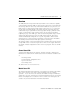
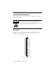
SLC 500™ RTD/Resistance Input Module Channel Status LEDs (Green) INPUT CHANNEL STA TUS 0 1 2 3 MODULE RTD / resistance 4 5 6 7 Module Status LED (Green) Removable Terminal Block Door Label RTD 0 Sense 0 Return 0 RTD 1 Sense 1 Return 1 RTD 2 Sense 2 Return 2 RTD 3 Sense 3 Return 3 RTD 4 Sense 4 Return 4 RTD 6 Sense 5 Return 5 RTD 6 Sense 6 Return 6 RTD 7 Sense 7 Return 7 1746-NR8 Cable Tie Slots Required Tools and Equipment Have the following tools and equipment ready • • • • • small blade scr
SLC 500™ RTD/Resistance Input Module 7 Electrostatic Damage Electrostatic discharge can damage semiconductor devices inside this module if you touch backplane connector pins or other sensitive areas. Guard against electrostatic damage by observing the following precautions. ATTENTION Electrostatic discharge can degrade performance or cause permanent damage. Handle the module as stated below. ! • Wear an approved wrist strap grounding device when handling the module.
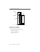
SLC 500™ RTD/Resistance Input Module Modular Chassis Considerations Place your RTD module in any slot of an SLC 500 modular chassis (except slot 0) or a modular expansion chassis. Slot 0 is reserved for the modular processor or adapter module. Fixed Expansion Chassis Considerations IMPORTANT The 2-slot, SLC 500 fixed I/O expansion chassis (1746-A2) supports many combinations of modules. The combinations that are not supported by the fixed expansion chassis are shown in the table below.
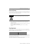
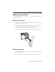
SLC 500™ RTD/Resistance Input Module 9 Module Installation and Removal When installing the module in a chassis, it is not necessary to remove the terminal block from the module. Module Installation Procedure 1. Align the circuit board of the RTD module with the card guides located at the top and bottom of the chassis. 2. Slide the module into the chassis until both top and bottom retaining clips are secured. Apply firm even pressure on the module to attach it to its backplane connector.
SLC 500™ RTD/Resistance Input Module Terminal Block Wiring and Removal The RTD module contains an 24-position, removable terminal block. The terminal pin-out is shown below. ATTENTION ! Disconnect power to the SLC before attempting to install, remove, or wire the removable terminal wiring block. To avoid cracking the removable terminal block, alternate the removal of the terminal block release screws. Terminal Wiring Terminal screws accept a maximum of one #14 AWG (2 mm2) wire.
SLC 500™ RTD/Resistance Input Module 11 Terminal Block Removal If the terminal block is removed, use the write-on label located on the side of the terminal block to identify the module location and type. To remove the terminal block: 1. Loosen the two terminal block release screws. 2. Grasp the terminal block at the top and bottom and pull outward and down. Wiring Considerations Follow the guidelines below when planning your system wiring.
SLC 500™ RTD/Resistance Input Module 2 Wire Interconnection Cable Shield (Frame Ground) Add Jumper RTD Return Belden #9501 Shielded Cable RTD 0 Sense 0 Return 0 RTD 1 Sense 1 Return 1 RTD 2 Sense 2 Return2 3 Wire Interconnection Cable Shield (Frame Ground) RTD Sense Return Belden #9533 Shielded Cable or Belden #83503 Shielded Cable RTD 0 Sense 0 Return 0 RTD 1 Sense 1 Return 1 RTD 2 Sense 2 Return2 4 Wire Interconnection Cable Shield (Frame Ground) RTD Sense Return Leave One Sensor Wire Open Bel
SLC 500™ RTD/Resistance Input Module IMPORTANT 13 The RTD module requires three wires to compensate for lead resistance error. We recommend that you do not use 2-wire RTDs if long cable runs are required, as it reduces the accuracy of the system. However, if a 2-wire configuration is required, reduce the effect of the lead wire resistance by using a lower gauge wire for the cable (for example, use AWG #16 instead of AWG #24). Also, use cable that has a lower resistance per foot of wire.
SLC 500™ RTD/Resistance Input Module Wiring Resistance Devices (Potentiometers) to the Module Potentiometer wiring requires the same type of cable as that for the RTD described on page 11. Potentiometers can be connected to the RTD module as a 2-wire interconnection as shown below.
SLC 500™ RTD/Resistance Input Module 15 Wiring Input Devices to the NR8 Module (See Step 4.) 2-Conductor Shielded Cable Signal Wire Signal Wire Signal Wire Foil Shield Signal Wire Drain Wire (See step 3.) Signal Wire (See Step 4.) Signal Wire 3-Conductor Shielded Cable Signal Wire Foil Shield Drain Wire Signal Wire Signal Wire Signal Wire (See step 3.) To wire your NR8 module, follow these steps. 1. At each end of the cable, strip some casing to expose the individual wires. 2.
SLC 500™ RTD/Resistance Input Module Specifications Electrical Specifications Backplane Current Consumption 100 mA at 5V dc 55 mA at 24V dc Backplane Power Consumption 1.82W maximum (0.5W at 5V dc, 1.
SLC 500™ RTD/Resistance Input Module 17 Physical Specifications LED Indicators Module ID Code Maximum Termination Wire Size Maximum Cable Impedance Terminal Block 9 green status indicators, one for each of 8 channels and one for module status 3508 - Class 1 12708 - Class 3 One 14 AWG wire per terminal 25 ohms maximum impedance for 3-wire RTD configuration (see Cable Specifications on page 11.
SLC 500™ RTD/Resistance Input Module Input Specifications RTD Types platinum, nickel, nickel iron, copper (For additional information on RTD types, see page 21.) Temperature °C or °F and 0.1°C or 0.1°F Scale (Selectable) Resistance Scale (Selectable) 1Ω or 0.1Ω for all resistance ranges except for 150Ω; or 0.1Ω or 0.01Ω for 150Ω potentiometer. Input Step Response Refer to the SLC 500™ RTD/Resistance Input Module User Manual, publication number 1747-UM003A.
SLC 500™ RTD/Resistance Input Module 19 RTD Temperature Ranges, Resolution, and Repeatability Input Type Resolution Repeatability -200°C to +850°C (-328°F to +1562°F) 0.1°C (0.1°F) ±0.2°C (±0.4°F) -200°C to +850°C (-328°F to +1562°F) -200°C to +850°C (-328°F to +1562°F) 0.1°C (0.1°F) ±0.2°C (±0.4°F) -200°C to +850°C (-328°F to +1562°F) -200°C to +390°C (-328°F to +698°F) 0.1°C (0.1°F) ±0.2°C (±0.4°F) 1000Ω -200°C to +850°C (-328°F to +1562°F) -200°C to +50°C (-328°F to +122°F) 0.1°C (0.
SLC 500™ RTD/Resistance Input Module Input Type Resistance Resistance Range (0.25 mA Excitation) Resistance Range (1.0 mA Excitation) Resolution Repeatability (28 Hz, 50/60 Hz) 150Ω 0 to 150Ω 0 to 150Ω 0.01Ω ±0.04Ω 500Ω 0 to 500Ω 0 to 500Ω 0.1Ω ±0.2Ω 1000Ω 0 to 1000Ω 0 to 1000Ω 0.1Ω ±0.2Ω 3000Ω 0 to 3000Ω 0 to 1200Ω 0.1Ω ±0.2Ω The module accuracy is dependent on the RTD/Resistance type, the excitation current, and the input filter selection.
SLC 500™ RTD/Resistance Input Module 21 RTD Accuracy and Temperature Drift Specifications Input Type Platinum (385)(3) Accuracy(1) (0.25 mA Excitation) ±0.5°C (±0.9°F) ±0.6°C (±1.1°F) ±0.7°C (±1.3°F) ±1.2°C (±2.2°F) ±0.4°C (±0.7°F) ±0.5°C (±0.9°F) ±0.6°C (±1.1°F) ±0.9°C (±1.6°F) ±0.5°C (±0.9°F) Accuracy(1) (1.0 mA Excitation) ±0.7°C (±1.3°F) ±0.7°C (±1.3°F) ±0.5°C (±0.9°F) ±0.4°C (±0.7°F) ±0.6°C (±1.1°F) ±0.6°C (±1.1°F) ±0.4°C (±0.7°F) ±0.3°C (±0.6°F) ±0.8°C (±1.4°F) Temperature Drift(2) (0.
SLC 500™ RTD/Resistance Input Module Notes: Publication 1746-IN007C-EN-P - December 2002
SLC 500™ RTD/Resistance Input Module 23 Notes: Publication 1746-IN007C-EN-P - December 2002
SLC 500 and MicroLogix are trademarks of Rockwell Automation. Belden is a trademark of Belden, Inc. Publication 1746-IN007C-EN-P - December 2002 Supersedes Publication 1746-IN007B-EN-P - May 2000 PN 40071-091-01(3) Copyright © 2002 Rockwell Automation. All rights reserved. Printed in the U.S.A.