SLC 500 RTD/Resistance Input Module 1746-NR4 User Manual
Important User Information Solid state equipment has operational characteristics differing from those of electromechanical equipment. Safety Guidelines for the Application, Installation and Maintenance of Solid State Controls (publication SGI-1.1 available from your local Rockwell Automation sales office or online at http://literature.rockwellautomation.com) describes some important differences between solid state equipment and hard-wired electromechanical devices.
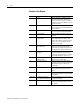
Summary of Changes New Information The information below summarizes the changes to this manual since the last revision. The table below lists sections that document new features and additional information about existing features and shows where to find this new information. 3 Change Page Moved terms and abbreviations from Preface to Glossary. Preface Updated programming examples to show RSLogix 500 software. Throughout manual Updated programming examples. Chapter 6 Updated programming examples.
Summary of Changes Notes: Publication 1746-UM008B-EN-P - December 2006
Table of Contents Preface Use This Manual . . . . . . . . . . . . . . . . . . . . Who Should Use This Manual . . . . . . . . . . Purpose of This Manual. . . . . . . . . . . . . . . Common Techniques Used in This Manual. . . . . . . . . . . . . . . . . . . . . . . . . . . . . . . . . . . . . . . . . . . . . . . . . . . . . . . . . 7 7 7 9 Chapter 1 Overview Description . . . . . . . . . . . . . . . . . . . . . . . . . . . . . . . . . . . . . 11 System Overview . . . . . . . . . . . . . . . .
Table of Contents Chapter 6 Ladder Programming Examples Device Configuration . . . . . . . . . . . . . . . . . . . Initial Programming. . . . . . . . . . . . . . . . . . . . . Dynamic Programming . . . . . . . . . . . . . . . . . . Verify Channel Configuration Changes . . . . . . . Interface to the PID Instruction . . . . . . . . . . . . Use the Proportional Counts Data Format with User-set Scaling. . . . . . . . . . . . . . . . . . . . . . . . Monitor Channel Status Bits. . . . . . . . . . . . . . .
Preface Use This Manual Read this preface to familiarize yourself with the rest of the manual. This preface covers the following topics: • • • • • Who Should Use This Manual Who should use this manual Purpose of this manual Terms and abbreviations Conventions used in this manual Allen-Bradley support Use this manual if you are responsible for designing, installing, programming, or troubleshooting control systems that use Allen-Bradley small logic controllers.
Preface Contents of this Manual Chapter Publication 1746-UM008B-EN-P - December 2006 Title Contents Preface Describes the purpose, background, and scope of this manual. Also specifies the audience for whom this manual is intended and defines key terms and abbreviations used throughout this book. 1 Overview Provides a hardware and system overview. Explains and illustrates the theory behind the RTD input module.
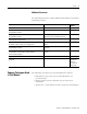
Preface 9 Additional Resources The following documents contain additional information on Rockwell Automation products.
Preface Notes: Publication 1746-UM008B-EN-P - December 2006
Chapter 1 Overview This chapter describes the four-channel 1746-NR4 RTD/Resistance Input Module and explains how the SLC controller gathers RTD (Resistance Temperature Detector) temperature or resistance-initiated analog input from the module. Included is: • a general description of the module’s hardware and software features. • an overview of system operation. For the rest of the manual, the 1746-NR4 RTD/Resistance Input Module is referred to as simply the RTD module.
Overview Simplified RTD Module Circuit Constant Current Source IC= 0.
Overview 13 RTD Compatibility The following table lists the RTD types you can use with the RTD module and gives each type’s associated temperature range, resolution, and repeatability specifications. RTD Unit Temperature Ranges, Resolution and Repeatability RTD Unit Type Temperature Range (0.5 mA excitation)(1) Temperature Range (2.0 mA excitation)(1) Resolution Repeatability 100 Ω -200…850 °C (-328…1562 °F) -200…850 °C (-328…1562 °F) 0.1 °C (0.2 °F) ±0.2 °C (±0.
Overview The exact signal range valid for each input type is dependent upon the excitation current magnitude that you select when configuring the module. IMPORTANT For details on excitation current, refer to page 119. This table shows the accuracy and temperature drift. Accuracy and Temperature Drift Specifications RTD Unit Type Accuracy (0.5 mA excitation)(1) Accuracy Temperature Drift Temperature Drift (0.2 mA excitation)(1) (0.5 mA excitation)(2) (0.2 mA excitation)(2) 100 Ω ±0.1 °C (±2.
Overview 15 When you are using 100 Ω or 200 Ω platinum RTD units with 0.5 mA excitation current, refer to the following important information about module accuracy. IMPORTANT Module accuracy, using 100 Ω or 200 Ω platinum RTD units with 0.5 mA excitation current, depends on the following criteria: • Module accuracy is ±0.6 °C (±33.08 °F) after you apply power to the module or perform an autocalibration at 25 °C (77 °F) ambient with module operating temperature at 25 °C (77 °F). • Module accuracy is ±(0.
Overview Resistance Device Compatibility The following table lists the resistance input types you can use with the RTD module and gives each type’s associated specifications. Resistance Input Specifications Input Type Resistance Range (0.5 mA excitation) Resistance Range (2.0 mA excitation) Accuracy(1) Temperature Drift Resolution Repeatability 150 Δ 0…150 Δ 0…150 Δ (2) (3) 0.01Δ x 0.04 Δ 500 Δ 0…500 Δ 0…500 Δ x 0.5 Δ x 0.014 Δ/ ° C (x 0.025 Δ/ ° F 0.01Δ x 0.
Overview 17 RTD Module Hardware 6 1 INPUT 5 MODULE ST ATUS 2 RTD/resistance SER ) UL LISTED IND. CONT . EQ. ) FOR HAZ. LOC. A196 CLASS I, GROUPS A, B, C AND D, DIV.
Overview System Overview The RTD module communicates to the SLC 500 processor through the parallel backplane interface and receives +5V dc and +24V dc power from the SLC 500 power supply through the backplane. No external power supply is required. You may install as many RTD modules in your system as the power supply can support.
Overview 19 System Operation The RTD module has three operational states. • Cycle power • Module operation • Error (module error and channel error) Cycle Power When you cycle the module’s power, the RTD module checks its internal circuits, memory, and basic functions via hardware and software diagnostics. During this time the module status LED indicator remains off. If no faults are found during the diagnostics, the module status LED indicator is on.
Overview The A/D convertors cycle between reading the RTD or resistance value, the lead wire resistance, and the excitation current. From these readings, an accurate temperature or resistance is returned to the user program. The RTD module is isolated from the chassis backplane and chassis ground. The isolation is limited to 500V dc. Optocouplers are used to communicate across the isolation barrier. Channel-to-channel common-mode isolation is limited to X 1 volt.
Overview 21 The status of each LED indicator, during each of the operational states (for example, powerup, module operation and error), is depicted in the following table. LED Indicator Status LED Indicator Cycle Power Module Operation (No Error) Module Error Channel Error Ch 0 Status Off(1) On/Off(2) Off Blinks Ch 1 Status Off(1) On/Off(2) Off Blinks Ch 2 Status Off(1) On/Off(2) Off Blinks Ch 3 Status Off(1) On/Off(2) Off Blinks Mod.
Overview Image Table Input Image Word Function Output Image Word Function 0 Channel 0 data 0 Channel 0 configuration 1 Channel 1 data 1 Channel 1 configuration 2 Channel 2 data 2 Channel 2 configuration 3 Channel 3 data 3 Channel 3 configuration 4 Channel 4 data 4 User-set Lower limit scale 0 5 Channel 5 data 5 User-set Upper limit scale 0 6 Channel 6 data 6 User-set Lower limit scale 1 7 Channel 7 data 7 User-set Upper limit scale 1 The Channel Configuration Words (
Chapter 2 Quick Start Guide This chapter helps you get started using the RTD module. The procedures included here assume that you have a basic understanding of SLC 500 products. You must: • understand electronic process control. • be able to interpret the ladder logic instructions for generating the electronic signals that control your application. Because this is a start-up guide, this chapter does not contain detailed explanations about the procedures listed.
Quick Start Guide Procedures Follow these procedures to get your RTD module installed and ready to use. Unpack the Module Unpack the module making sure that the contents include: • RTD module, catalog number 1746-NR4. • Installation instructions, publication 1746-IN012. If the contents are incomplete contact your Allen-Bradley representative for assistance. Determine Power Requirements Review the requirements of your system to see that your chassis supports placement of the RTD module.
Quick Start Guide 25 Insert the Module ATTENTION Never install, remove, or wire modules with power applied to the chassis or devices wired to the module. For more information refer to chapter 3, Install and Wire. Make sure system power is off; then insert the RTD module into your 1746 chassis. In this example procedure, local slot 1 is selected.
Quick Start Guide RTD Connections to Terminal Block For details on wiring an RTD unit to the module, see chapter 3. Two Wire RTD Interconnection Add jumper.
Quick Start Guide 27 Two-wire Potentiometer Connections to Terminal Block For details on wiring an RTD unit to the module, see chapter 3. Cable Shield Potentiometer Add jumper. Shield Chl 0 RTD RTD Chl 0 Sense Return Chl 0 Return Belden #9501 Shielded Cable Potentiometer wiper arm can be connected to either the RTD or return terminal depending on whether the user wants increasing or decreasing resistance. Add jumper.
Quick Start Guide Three-wire Potentiometer Connections to Terminal Block For details on wiring an RTD to the module, see chapter 3. Cable Shield Run RTD unit and sense wires from module to potentiometer terminal and tie them to one point. Shield Chl 0 RTD Potentiometer RTD Sense Chl 0 Sense Return Chl 0 Return Belden #83503 or Belden #9533 Shielded Cable Potentiometer wiper arm can be connected to either the RTD or return terminal depending on whether you want increasing or decreasing resistance.
Quick Start Guide 29 Configure the Module Determine the operating parameters for channel 0. In this example, the figure shows the channel 0 configuration word defined with all defaults (0) except for channel enable (bit 11). The addressing reflects the location of the module as slot 1. For details on how to configure the module for your application, refer to chapter 4 and chapter 5. A configuration worksheet is included on page 132 to assist you in channel configuration.
Quick Start Guide Program the Configuration Follow these steps to complete the programming necessary to establish the new configuration word setting in the previous step. 1. Create integer file N10 using the memory map function. Integer file N10 should contain one element for each channel used. For this example we only need one, N10:0. 2. Enter the configuration parameters for channel 0 into integer N10:0. In this example, all the bits of N10:0 are zero except for the channel enable (N10:0/11). 3.
Quick Start Guide 31 Write Remaining Ladder Logic The Channel Data Word contains the information that represents the temperature value or resistance value of the input channel. Write the remainder of the ladder logic program that specifies how your RTD/resistance input data is processed for your application. In this procedure, the addressing reflects the location of the module as slot 1. Input Image Detail SLC 500 Controller Data Files Input Image (8 words) Output Image Address I:1.
Quick Start Guide Program Functional Check (Optional) Monitor the status of input channel 0 to determine its configuration setting and operational status. This is useful for troubleshooting when the blinking channel LED indicator indicates that an error has occurred. If the Module Status LED indicator is off, or if the Channel 0 LED indicator is off or blinking, refer to chapter 7. For more information see chapter 5, chapter 7, and chapter 8.
Chapter 3 Install and Wire the Module This chapter tells you how to: • • • • • avoid electrostatic damage. determine the RTD module’s chassis power requirement. choose a location for the RTD module in the SLC chassis. install the RTD module. wire the RTD module’s terminal block. If this product has the CE mark it is approved for installation within the European Union and EEA regions. It has been designed and tested to meet the following directives.
Install and Wire the Module • Touch a grounded object to rid yourself of electrostatic charge before handling the module. • Handle the module from the front, away from the backplane connector. Do not touch backplane connector pins. • Keep the module in its static-shield bag when not in use, or during shipment. NR4 Power Requirements The RTD module receives its power through the SLC 500 chassis backplane from the fixed or modular +5V dc/+24V dc chassis power supply.
Install and Wire the Module Module Location in Chassis 35 This section contains information on module location in modular and fixed chassis. Modular Chassis Considerations Place your RTD module in any slot of an SLC 500 modular chassis (except slot 0) or a modular expansion chassis. Slot 0 is reserved for the modular processor or adapter modules. Fixed Expansion Chassis Considerations IMPORTANT The 2-slot, SLC 500 fixed I/O expansion chassis (1746-A2) supports only specific combinations of modules.
Install and Wire the Module Fixed Controller Compatibility Table Modules IA4 IA8 IA16 IM4 IM8 IM16 OA8 OA16 OAP12 IB8 IB16 IV8 IV16 IG16 IH16 OV8 OV16 OB8 OBP8 OG16 OW4 OW8 OW16 IO4 IO8 IO12 NI4 NI8 NIO4I NIO4V FIO4I FIO4V DCM HS OB16 OB16E IN16 BASn BAS OB32 OV32 IV32 IB32 Publication 1746-UM008B-EN-P - December 2006 NR4 • • • • • • • • • • • • • • • • • • • • • • (2) • • • • • • • • • • • • • • • • • • (1) 5V dc (Amps) 0.035 24V dc (Amps) - 0.050 0.085 0.035 0.050 0.085 0.185 0.370 0.370 0.
Install and Wire the Module 37 Fixed Controller Compatibility Table Modules OX8 NO4I NO4V ITB16 ITV16 IC16 KE KEn OBP16 OVP16 NT4 NR4 HSTP1 NR4 • Δ(3) • • • • • • • • • • • 5V dc (Amps) 0.085 0.055 24V dc (Amps) 0.090 0.195 0.055 0.085 0.085 0.085 0.150 0.150 0.250 0.250 0.060 0.050 0.200 0.145 0.40 0.145 0.040 0.050 - (1) A dot indicates a valid combination. (2) No symbol indicates an invalid combination. (3) A triangle indicates an external power supply is required.
Install and Wire the Module Module Installation and Removal When installing the module in a chassis, it is not necessary to remove the terminal block from the module. However, if the terminal block is removed, use the write-on label located on the side of the terminal block to identify the module location and type.
Install and Wire the Module 39 Install the Module 1. Align the circuit board of the RTD module with the card guides located at the top and bottom of the chassis. Top and Bottom Module Release(s) Card Guide 2. Slide the module into the chassis until both top and bottom retaining clips are secured. Apply firm even pressure on the module to attach it to its backplane connector. Never force the module into the slot. 3. Cover all unused slots with the Card Slot Filler, catalog number 1746-N2.
Install and Wire the Module Terminal Wiring The RTD module contains an 18-position, removable terminal block. The terminal pin-out is shown in RTD Connections to Terminal Block on page 42. Disconnect power to the SLC before attempting to install, remove, or wire the removable terminal wiring block. ATTENTION To avoid cracking the removable terminal block, alternate the removal of the terminal block release screws. Terminal Block Shield Channel 0 RTD Release Screw Max. Torque = 0.6 Nm (5.
Install and Wire the Module 41 For a three-wire configuration, the module can compensate for a maximum cable length associated with an overall cable impedance of 25 ohms. IMPORTANT Details of cable specifications are shown on page 122. As shown in RTD Connections to Terminal Block on page 42, three configurations of RTDs can be connected to the RTD module, namely: • two-wire RTD, which is composed of two RTD lead wires (RTD and Return).
Install and Wire the Module • Tighten terminal screws using a flat or cross-head screwdriver. Each screw should be turned tight enough to immobilize the wire’s end. Excessive tightening can strip the terminal screw. The torque applied to each screw should not exceed 0.565 Nm (5 in-lb) for each terminal. • Follow system grounding and wiring guidelines found in your SLC 500 Installation and Operation Manual, publication 1747-UM011.
Install and Wire the Module 43 When using a three-wire configuration, the module compensates for resistance error due to lead wire length. For example, in a three-wire configuration, the module reads the resistance due to the length of one of the wires and assumes that the resistance of the other wire is equal. If the resistances of the individual lead wires are much different, an error may exist. The closer the resistance values are to each other, the greater the amount of error that is eliminated.
Install and Wire the Module Two-wire Potentiometer Connections to Terminal Block Cable Shield Potentiometer Add jumper. Shield Chl 0 RTD RTD Chl 0 Sense Chl 0 Return Return Belden #9501 Shielded Cable Potentiometer wiper arm can be connected to either the RTD or return terminal depending on whether the user wants increasing or decreasing resistance. Add jumper.
Install and Wire the Module 45 Three-wire Potentiometer Connections To Terminal Block Cable Shield Shield Run RTD and sense wires from module to potentiometer terminal and tie them to one point. RTD Potentiometer Chl 0 RTD Sense Chl 0 Sense Return Chl 0 Return Belden #83503 or Belden #9533 Shielded Cable Potentiometer wiper arm can be connected to either the RTD or return terminal depending on whether the user wants increasing or decreasing resistance.
Install and Wire the Module Follow these steps to wire your 1746-NR4 module. 1. At each end of the cable, strip some casing to expose the individual wires. 2. Trim the signal wires to 5.08 cm (2 in.) lengths. Strip about 4.76 mm (3/16 in.) of insulation away to expose the end of the wire. 3. At one end of the cable twist the drain wire and foil shield together, bend them away from the cable, and apply shrink wrap. Then earth ground at the shield terminal. 4.
Install and Wire the Module Calibration 47 The accuracy of a system that uses the RTD module is determined by: • the accuracy of the RTD. • resistance mismatch of the cable wires that connect the RTD to the module. • the accuracy of the RTD module. For optimal performance at the customer site, the RTD module is calibrated at the factory prior to shipment.
Install and Wire the Module You can command your module to perform an auto-calibration cycle by disabling a channel, waiting for the channel status bit to change state (1 to 0) and then re-enabling that channel. Several scan cycles are required to perform an auto-calibration (refer to page 4-11). It is important to remember that during auto-calibration the module is not converting input data.
Install and Wire the Module 49 5. Use the RTD module to determine the temperature equivalent to the fixed precision resistor and cable combination. 6. Calculate the offset value by subtracting the calculated calibration temperature from the measured temperature. 7. Reconnect the RTD to the cable. 8. Use ladder logic to apply (subtract) the offset from the measured temperature to obtain corrected temperature.
Install and Wire the Module Notes: Publication 1746-UM008B-EN-P - December 2006
Chapter 4 Preliminary Operating Considerations This chapter explains how the RTD module and the SLC processor communicate through the module’s input and output image. It lists the preliminary setup and operation required before the RTD module can function in a 1746 I/O system. Topics discussed include how to: • • • • • enter the module ID code. address your RTD module. select the proper input filter for each channel. calculate the RTD module update time.
Preliminary Operating Considerations Module Addressing The memory map displays how the output and input image tables are defined for the RTD module. Bit 15 RTD Module Image Table SLC 5/0X Data Files Slot e Output Scan Output Image Output Image 8 Words Output Image Bit 0 Address Channel 0 Configuration Word Word 0 O:e.0 Channel 1 Configuration Word Word 1 O:e.1 Channel 2 Configuration Word Word 2 O:e.2 Channel 3 Configuration Word Word 3 O:e.
Preliminary Operating Considerations EXAMPLE 53 If you want to configure channel 2 on the RTD module located in slot 4 in the SLC chassis, your address would be O:4.2 Slot File Type Word O:4.2 Element Delimiter Word Delimiter Chapter 5, Channel Configuration, Data, and Status, gives you detailed bit information about the content of the data word and the status word.
Preliminary Operating Considerations Chapter 5, Channel Configuration, Data, and Status, gives you detailed bit information about the content of the data word and the status word. The RTD module uses a digital filter that provides noise rejection for the input signals. The digital filter is programmable, allowing you to select from four filter frequencies for each channel. The digital filter provides the highest noise rejection at the selected filter frequency.
Preliminary Operating Considerations 55 Effective Resolution The effective resolution for an input channel depends upon the filter frequency selected for that channel. This table displays the effective resolution for the various input types and filter frequencies. Effective Resolution Input Type Filter Frequency 10 Hz 50 Hz 60 Hz 250 Hz 100 Ω Pt RTD (385)(1) ±0.1 °C (±0.2 °F) ±0.2 °C (±0.4 °F) ±0.2 °C (±0.4 °F) ±0.4 °C (±0.7 °F) 200 Ω Pt RTD (385)(1) ±0.1 °C (±0.2 °F) ±0.2 °C (±0.4 °F) ±0.
Preliminary Operating Considerations Channel Cut-off Frequency The channel filter frequency selection determines a channel’s cut-off frequency, also called the -3 dB frequency. The cut-off frequency is defined as the point on the input channel frequency response curve where frequency components of the input signal are passed with 3 dB of attenuation. All frequency components at or below the cut-off frequency are passed by the digital filter with less than 3 dB of attenuation.
Preliminary Operating Considerations 57 50 Hz Filter Notch Frequency 0 -3 dB -20 -40 -60 -80 -100 Amplitude (in dB) -120 -140 -160 -180 -200 0 50 100 150 200 250 300 Hz Frequency 13.1 Hz Frequency Response 60 Hz Filter Notch Frequency 0 -3 dB -20 -40 -60 Amplitude (in dB) -80 -100 -120 -140 -160 -180 -200 0 60 120 180 240 300 Hz Frequency Frequency Response 15.72 Hz 250 Hz Filter Notch Frequency -3 dB 0 -20 -40 -60 -80 -100 Amplitude (in dB) -120 -140 -160 -180 -200 0 250 65.
Preliminary Operating Considerations Scanning Process and Channel Timing This section shows how to determine the channel update time and channel autocalibration time. In addition, the scanning process is briefly described. The RTD module channel update time is defined as the time required for the module to sample and convert (scan) the input signal of an enabled input channel and make the resulting data value available to the SLC processor for update.
Preliminary Operating Considerations 59 Channel scanning is sequential and always occurs starting with the lowest numbered enabled channel and proceeding to the next highest numbered channel, for example, channel 0 - channel 1 - channel 2 channel 3 - channel 0 - channel 1. Channel scan time is a function of the filter frequency.
Preliminary Operating Considerations Scanning Cycle Channel 1 Channel 0 Start Update Channel 1 data word. Calculate Channel 1 data. Wait for Channel 0 A/D conversion. Configure and start Channel 0 A/D. Read Channel 1 A/D. Read Channel 0 A/D. Configure and start Channel 1 A/D. Wait for Channel 1 A/D conversion. Calculate Channel 0 data. Update Channel 0 data word.
Preliminary Operating Considerations Channel Turn-on, Turn-off, and Reconfiguration Time 61 The table below gives you the turn-on, turn-off, and reconfiguration times for enabling or disabling a channel. Function Description Duration Turn-on Time The time it takes to make converted data available in the data word and to set the status bit (transition from 0 to 1) in the status word, after setting the enable bit in the configuration word.
Preliminary Operating Considerations Input Response When a RTD slot is disabled, the RTD module continues to update its input image table. However, the SLC processor does not read inputs from a module that is disabled. Therefore, when the processor disables the RTD module slot, the module inputs appearing in the processor input image remain in their last state and the module’s updated image table is not read.
Chapter 5 Channel Configuration, Data, and Status This chapter examines the channel configuration word and the channel status word bit by bit. It explains how the module uses configuration data and generates status during operation. It gives you information about how to: • configure a channel. • examine channel input data. • check a channel’s status. Channel Configuration The channel configuration word is a part of the RTD module’s output image.
Channel Configuration, Data, and Status Module default settings for configuration words 0…7 are all zeros. Scaling defaults are explained on page 78 under the explanation for the Scaling Select (Bits 13-14). The channel configuration word consists of bit fields, the settings of which determine how the channel operates. This procedure looks at each bit field separately and helps you configure a channel for operation. Refer to the Channel Configuration Word (O:e.0 through O:e.
Channel Configuration, Data, and Status 65 6. If the channel is configured for RTD inputs and engineering units data format, determine if you want the channel data word to read in ° C or ° F and enter a one or a zero in bit 8 (Temperature Units) of the configuration word. If the channel is configured for a resistance input, this field is ignored. 7.
Channel Configuration, Data, and Status Channel Configuration Word (O:e.0 through O:e.
Channel Configuration, Data, and Status 67 Input Type Selection (Bits 0…3) The input type bit field lets you configure the channel for the type of input device you have connected to the module. Valid input devices are shown in the Channel Configuration Word (O:e.0 through O:e.3) Bit Definitions table. Data Format Selection (Bits 4 and 5) The data format bit field lets you define the format for the channel data word contained in the module input image.
Channel Configuration, Data, and Status Using Scaled-for-PID and Proportional Counts Formats The RTD module provides eight options for displaying input channel data. These are 0.1 °F, 0.1 °C, 1 °F, 1 °C, 0.1 Ω, 1 Ω, Scaled-for-PID, and Proportional Counts. The first six options represent real engineering units and do not require explanation. The Scaled-for-PID selection allows you to directly interface RTD Data into a PID instruction without intermediate scale operations.
Channel Configuration, Data, and Status 69 The Linear Relationship Between Temperature and PID Counts graph shows the linear relationship between output counts and temperature when one uses scaled–for–PID data format. Linear Relationship Between Temperature and PID Counts Counts 16383 ±200 °C 630 °C °C Proportional Counts Data Format If the user selects proportional counts data format, the data word for that channel is a number between -32,768 and 32,767.
Channel Configuration, Data, and Status Linear Relationship Between Temperature and Proportional Counts Counts + 32,767 ±200 °C 630 °C ± 32,768 Publication 1746-UM008B-EN-P - December 2006 °C
Channel Configuration, Data, and Status 71 Scaling Examples The following examples are using the default scaling ranges. Scaled-for-PID to Engineering Units Equation Engr Units Equivalent = SLOW + [(SHIGH - SLOW) x (Scaled-for-PID value displayed / 16383)] Assume that the input type is an RTD, Platinum (200Ω, a = 0.00385 °C, range = -200 °C…850 °C), scaled-for-PID display type. Channel data = 3421. Want to calculate °C equivalent.
Channel Configuration, Data, and Status The Data Formats for RTD Temperature Ranges for 0.5 and 2.0 mA Excitation Current table shows the temperature ranges of several 1746-NR4 RTDs. The table applies to both 0.5 and 2.0 mA excitation currents.
Channel Configuration, Data, and Status 73 Data Format for 10 Ω(1) Copper 426 RTD Data Format Excitation Current Engineering Units x 1 Engineering Units x 10 Scaled-for-PID Proportional Counts (Defaults) 0.1 °C 0.1 °F 1.0 °C 1.0 °F 0.5 mA not allowed --- --- --- --- --- --- 2.0 mA -1000…2600 -1480…5000 -100…260 -148…500 0…16,383 -32,768…32,767 (1) Actual value at 0 °C (32 °F) is 9.042 Ω per SAMA standard RC21-4-1966.
Channel Configuration, Data, and Status The Channel Data Word Resolution for RTDs table shows the data resolution provided by the 1746-NR4 for RTD input types using the various data formats. Channel Data Word Resolution for RTDs Data Format (Bits 4 and 5)(1) RTD Input Type Engineering Units x 1 °C °F Engineering Units x 10 °C °F Proportional Counts (Defaults) Scaled-for-PID °C °F °C °F 100 Ω Platinum 385 0.1 °C/step 0.1 °F/step 1 °C/step 1 °F/step 0.0641 °C/step 0.1154 °F/step 0.
Channel Configuration, Data, and Status 75 Channel Data Word Resolution for 500 Ω, 1000 Ω, and 3000 Ω Resistance Inputs Data Format (Bits 4 and 5) Resistance Input Type Engineering Units x 1 Engineering Units x 10 Ohms Ohms Scaled-for-PID Ohms Proportional Counts (Defaults) Ohms 500 Ω 0.1 Ω / step 0.1 Ω / step 0.0305 Ω / step 0.0076 Ω / step 1000 Ω 0.1 Ω / step 0.1 Ω / step 0.0610 Ω / step 0.0153 Ω / step 3000 Ω 0.1 Ω / step 0.1 Ω / step 0.1831 Ω / step 0.
Channel Configuration, Data, and Status Temperature Units Selection (Bit 8) The Bit Descriptions for Temperature Units Selection table shows the description for bit 8. The temperature units bit lets you select temperature engineering units in °C or °F for RTD input types. This bit field is only active for RTD input types. It is ignored when the resistance input type is selected.
Channel Configuration, Data, and Status 77 When set (1), the channel enable bit is used by the module to read the configuration word information you have selected. While the enable bit is set, modification of the configuration word may lengthen the module update time for one cycle. If any change is made to the configuration word, the change must be reflected in the status word before new data is valid. Refer to Channel Status Checking on page 82.
Channel Configuration, Data, and Status Scaling Select (Bits 13-14) If you selected proportional counts as the format for your input data, you can enter a scaling range that ensures your data is scaled within a range appropriate for your use. You can use words 4 and 5 to define one range and words 6 and 7 to define a second range. The Bit Descriptions for Scaling Selection table gives the descriptions for bits 13 and 14.
Channel Configuration, Data, and Status 79 User-set Scaling Proportional Counts - The second case to consider is User-set Scaling using proportional counts when the scaling select bits 13 and 14 are set to 01 or 10. Here you can configure the module to scale the data word to something other than -32,768 to 32,767. However, the maximum range remains -32,768 to +32,767.
Channel Configuration, Data, and Status User-set Scaling Using Proportional Counts Data Format Selected Proportional Counts Data Format Selected 1000Ω Pot SelectedConfigurationWords 4 & 5 for Scaling O:e.3 0 15 0 1 0 1 0 0 0 0 0 1 1 1 1 1 0 0 Lowerscale limit set for3 O:e.4 0 15 0 0 0 0 0 0 0 0 0 0 0 0 0 1 1 0 Upper scale limit set for 50 O:e.5 0 15 0 0 0 0 0 0 0 0 0 1 1 0 0 1 0 0 CH 3 Configuration W ord Range 0 O:e.
Channel Configuration, Data, and Status 81 Unused (Bit 15) Bit 15 is not used. Verify that this bit is always cleared (0). The actual RTD or resistance input sensor values reside in I:e.0 through I:e.3 of the RTD module input image file. The data values present depend on the input type and data format you have selected in your configuration for the channel. When an input channel is disabled, its data word is reset (0).
Channel Configuration, Data, and Status Channel Status Checking The channel status word is a part of the RTD module’s input image. Input words 4…7 correspond to and contain the configuration status of channels 0, 1, 2, and 3 respectively. You can use the data provided in the status word to determine if the data word for any channel is valid per your configuration in O:e.0 through O:e.3. For example, whenever a channel is disabled (O:e.x/11 = 0), its corresponding status word shows all zeros.
Channel Configuration, Data, and Status 83 Channel 0…3 Status Word (I:e.4 through I:e.
Channel Configuration, Data, and Status IMPORTANT The status bits reflect the settings that were made in the configuration word. However, two conditions must be true if the status reflected is to be accurate. • The channel must be enabled. • The channel must have processed any new configuration data. Input Type Status (Bits 0…3) The input type bit field indicates what type of input device you have configured for the channel.
Channel Configuration, Data, and Status 85 Channel Filter Frequency (Bits 9 and 10) The channel filter frequency bit field reflects the filter frequency you selected in bits 9…10 of the configuration word when the channel is enabled. This feature is active for all input types. If the channel is disabled, these bits are cleared (0). Channel Enable Status (Bit 11) The channel enable status bit indicates whether the channel is enabled or disabled.
Channel Configuration, Data, and Status Out-of-range Error (Bit 14) This bit is set (1) whenever a configured channel detects an over-range condition for the input channel data, regardless of input type. This bit is also set (1) whenever the module detects an under-range condition when the input type is an RTD.
Chapter 6 Ladder Programming Examples Earlier chapters explained how the configuration word defines the way a channel operates. This chapter shows the programming required to enter the configuration word into the processor memory. It also provides you with segments of ladder logic specific to unique situations that might apply to your programming requirements. The example segments include: • • • • • • • Device Configuration initial programming of the configuration word.
Ladder Programming Examples Application Setup 1746-NR4 RTD Module 1746-OB8 DC Output Module (Sourcing) 1746-IB8 DC Input Module (Sinking) RTD 0 SLC Processor Slot # 0 1 2 RTD 1 3 RTD 2 Pilot Light O:2/1 RTD 3 Pilot Light O:2/3 Pilot Light O:2/0 Ch. 0 Alarm Ch. 1 Alarm Ch. 2 Alarm Ch.
Ladder Programming Examples 89 Configuration Word Setup 15 14 13 12 11 10 9 8 7 6 5 4 3 2 1 0 0 0 0 1 0 0 1 0 0 0 1 0 0 0 0 1 Bit Number Bit Setting Configures Channel For: 200 Ω Platinum RTD (385) Eng. Units x 10 (1 °F/ step) Broken Input (Zero Data Word) Degrees Fahrenheit (°F) 10 Hz Filter Frequency Channel Enabled 2.
Ladder Programming Examples Programming Procedure 1. Create integer file N10 in your programming software. Integer file N10 should contain four elements (N10:0 through N10:3). 2. Enter the configuration parameters for all four RTD channels into a source integer data file N10. Refer to the Configuration Word Setup for the bit values. See page 128 for a channel configuration worksheet. 3.
Ladder Programming Examples Dynamic Programming 91 The programming example explains how to change data in the channel configuration word when the channel is currently enabled. EXAMPLE Execute a dynamic configuration change to channel 2 of the RTD module located in slot 3 of a 1746 chassis. Change from monitoring the temperature in °F to monitoring in °C. Programming Procedure 1. Create a new element in integer file N10 using the memory map function.
Ladder Programming Examples Verify Channel Configuration Changes When executing a dynamic channel configuration change, there is always a delay from the time the ladder program makes the change to the time the RTD module gives you a data word using that new configuration information. Therefore, it is very important to verify that a dynamic channel configuration change took effect in the RTD module. This is particularly important if the channel being dynamically configured is used for control.
Ladder Programming Examples 93 Program to Verify Configuration Word Data Changes - Continued Check that the configuration written to channel 2 is being echoed back in channel 2's status word. EQU Rung 2:4 EQUAL Source A N7:1 Source B 0 Data valid B3 ( ) 3 Rung 2:5 END Interface to the PID Instruction The RTD module was designed to interface directly to the SLC 5/02, SLC 5/03, SLC 5/04, and SLC 5/05 PID instruction without the need for an intermediate scale operation.
Ladder Programming Examples Rung 2:0 Initialize NR4 Channel 0 First Pass Bit S:1 ] [ 15 Rung 2:1 Channel0 Status I:3.4 ] [ 11 Rung 2:2 MOV MOVE Source N10:0 Dest O:3.0 Entering address N11:0 allocates elements N11:0 to N11:22 for required Control Block file length of 23 words. The Process Variable is address I:3.0, which stores the value of input data word 0 (channel 0). Output of the PID instruction is stored at address N11:23 (Control Variable address).
Ladder Programming Examples Use the Proportional Counts Data Format with User-set Scaling 95 The RTD module can be set up to return data to the user program that is specific to the application. Assume that you control the line speed of a conveyor using a 1000 Ω potentiometer connected to channel 0 of the RTD module. The line speed will vary between 3 ft/m when the potentiometer is at 0 Ω and 50 ft/m when the potentiometer is at 1000 Ω.
Ladder Programming Examples Monitor Channel Status Bits The Programming to Monitor Channel Status ladder diagram shows how you could monitor the open- and short-circuit error bits of each channel and set an alarm in the processor if one of the RTDs or resistance-input devices (such as a potentiometer) opens or shorts. An open-circuit error can occur if the RTD or resistance-input device breaks or one of the RTD or resistance-input device wires get cut or disconnected from the terminal block.
Ladder Programming Examples Invoke Autocalibration 97 Autocalibration of a channel occurs whenever: • a channel first becomes enabled. • when a change is made to its input type, filter frequency, or excitation current. • whenever an operating channel is disabled and re-enabled using its enable bit.
Ladder Programming Examples Programming to Invoke Autocalibration Rung 2:0 Condition for Autocalibration I:1 ] [ 1 Channel 0 Enable B3 [OSR] 0 O:3.0 (U) 11 Channel 0 Flag B3 (L) 1 Rung 2:1 Channel 0 Status Channel 0 Flag I:3.4 ]/[ 11 B3 ] [ 1 Channel 0 Enable O:3.0 (L) 11 Channel 0 Flag B3 (U) 1 IMPORTANT Publication 1746-UM008B-EN-P - December 2006 The RTD module responds to processor commands much more frequently than it updates its own LED indicators.
Chapter 7 Module Diagnostics and Troubleshooting Introduction This chapter describes troubleshooting using the channel status LED indicators as well as the module status LED indicator. A troubleshooting flowchart is shown on page 105. The flowchart explains the types of conditions that might cause an error to be reported and gives suggestions on how to resolve the problem. Major topics include the following: • • • • • • • Module Operation vs. Channel Operation Module operation vs.
Module Diagnostics and Troubleshooting A series of internal diagnostic self-tests is performed when power is applied to the module. The module status LED indicator and all channel status LED indicators remain off while power is applied. If any diagnostic test fails, the module enters the module error state. If all tests pass, the module status LED indicator is turned on and the channel status LED indicator is turned on for the respective enabled channel.
Module Diagnostics and Troubleshooting 101 The LED Indicator Status Description table explains the function of the channel status LED indicators while the module status LED indicator is turned on. LED Indicator Status Description If Module Status LED Indicator is And Channel Status LED Indicator is Indicated Condition Corrective Action On On Channel enabled No action required.
Module Diagnostics and Troubleshooting Error Codes The error codes applicable to the RTD module range from 50H to 5AH. These are non-recoverable errors. For a description of the error codes, refer to SLC 500 Instruction Set Reference Manual (Publication 1747–RM001).
Module Diagnostics and Troubleshooting 103 Open- and Short-circuit Detection An open- or short-circuit test is performed on all enabled channels on each scan. Whenever an open-circuit or short-circuit condition occurs, the channel LED indicator blinks and bit 13 of the channel status word is set. These are possible causes of an open or short circuit. • The RTD or potentiometer may be broken. • A RTD or potentiometer wire may be loose or cut.
Module Diagnostics and Troubleshooting Possible causes of an out-of-range condition include the following: • The temperature is too hot or too cold for the RTD unit being used. • Wrong RTD unit used for type/configuration selected. • Bad potentiometer or RTD unit. • Signal input from either potentiometer or RTD unit is beyond the user-set scaling range. Module Status LED Indicator (Green) The module status LED indicator is used to indicate module-related diagnostic or operating errors.
Module Diagnostics and Troubleshooting 105 Troubleshooting Flowchart Check LED indicators on module. Module Status LED indicator is off. Module Status LED indicator is on. Module fault condition. Normal module operation. Check to see that module is seated properly in chassis. Cycle power. End Channel Status LED indicator is off. Channel Status LED indicators blinking Channel is not enabled. Fault condition. Channel Status LED indicator is on. Channel is enabled and working properly. .
Module Diagnostics and Troubleshooting Replacement Parts The RTD module has the following replaceable parts. Parts List Contact Rockwell Automation Part Part Number Replacement Terminal Block 1746-RT25G Replacement Terminal Cover 1746-R13 series G 1746-NR4 User Manual 1746-6.7 If you need to contact Rockwell Automation for assistance, please have the following information available when you call.
Chapter 8 Application Examples This chapter provides two application examples to help you use the RTD input module. They are defined as a: • basic example. • supplementary example. The basic example builds on the configuration word programming provided in chapter 6 to set up one channel for operation. This setup is then used in a typical application to display temperature. The supplementary example demonstrates how to perform a dynamic configuration of all four channels.
Application Examples Channel Configuration Configure the RTD channel with the following setup: • • • • • 200 Ω Platinum RTD °F in whole degrees Zero data word in the event of an open or short circuit 10 Hz input filter 2.
Application Examples 0110 = 500 Ω Pt. (3916) 0111 = 1000 Ω Pt. (3916) 1000 = 10 Ω Cu (426)(1) 1001 = 120 Ω Ni (618)(2) 1010 = 120 Ω Ni (672) 1011 = 604 Ω Ni-Fe (518) Bits 0…3 0000 = 100 Ω Pt. (385) 0001 = 200 Ω Pt. (385) 0010 = 500 Ω Pt. (385) Input Type Selected 0011 = 1000 Ω Pt. (385) 0100 = 100 Ω Pt. (3916) 0101 = 200 Ω Pt.
Application Examples Program to Convert °F to BCD Initialize Channel 0 of RTD Module. Rung 2.0 First Pass Bit MOV S:1 ] [ 15 MOVE Source N10:0 Dest O:3.0 Rung 2.1 Convert the channel 0 data word (degrees F) to BCD values and write this to the LED display. If channel 0 is ever disabled, a zero is written to the display . TOD TO BCD Source Dest I:3.0 N7:0 MVM ➀ MASKED MOVE Source Mask Dest N7:0 0FFF O:2.
Application Examples Supplementary Example 111 This example provides the application setup, channel configuration, and program setup. Application Setup (Four Channels °C ↔ °F) Device Configuration for Displaying Many RTD Outputs shows how to display the temperature of several different RTD units at one annunciator panel. A selector switch (I:2/0) allows the operator to choose between displaying data in °C and °F.
Application Examples Channel Configuration See completed worksheet in Channel Configuration Worksheet (With Settings Established) on page 113. Configuration setup for ambient RTD includes the following: • • • • • • • channel 0 604 Ω Nickel/Iron (518) display temperature to tenths of a degree Celsius zero data word in the event of an open or short circuit 60 Hz input filter to provide 60 Hz line noise rejection use 2.
Application Examples 113 Channel Configuration Worksheet (With Settings Established) 0 Bit Number 15 14 13 12 11 10 9 8 7 6 5 4 3 2 1 0 0 0 0 1 1 0 0 0 0 0 0 1 0 1 1 Channel 0 (Ambient) 0 0 0 0 1 1 0 0 0 0 0 0 0 0 0 1 Channel 1 (Bath) 0 0 0 1 1 1 0 0 0 0 0 0 0 0 1 1 Channel 2 (Steam) 0 0 0 0 1 1 0 0 0 0 0 0 0 0 0 1 Channel 3 (Chilled H2O) Input Type Select Data Format Select Broken Input Select Temperature Units Select Fi
Application Examples Program Setup and Operation Summary 1. Set up two configuration words in memory for each channel, one for °C and the other for °F. Channel Configuration Word Allocation °F °C 0 N10:0 N10:4 1 N10:1 N10:5 2 N10:2 N10:6 3 N10:3 N10:7 2. When the position of the degrees selector switch changes, write the appropriate channel configuration to the RTD module.
Application Examples 115 Program Listing The first two rungs of this program send the correct channel setup information to the RTD module based on the position of the degrees selector switch. Program to Display Data on LED Displays Rung 2.0 If the degrees selector switch is turned to the Fahrenheit position, set up all four channels to read in degrees Fahrenheit. Degrees Selector Switch ± Fahrenheit I:2.0 ] [ 0 Configure R TD Module Channels B3 OSR 0 COP COPY FILE Source Dest Length #N10:0 #O:1.
Application Examples Rung 2.4 Write RTD Module Steam Temperature to Display TOD Rung 2.5 I:1.2 Dest O:5.0 Write RTD Module Chilled Temperature to Display TOD Rung 2.6 END Publication 1746-UM008B-EN-P - December 2006 TO BCD Source TO BCD Source I:1.3 Dest O:6.
Appendix A Specifications This appendix lists the specifications for the 1746-NR4 RTD Input Module. 1746-NR4 Electrical Specifications 117 Backplane current consumption 50 mA at 5V dc 50 mA at 24V dc Backplane power consumption 1.5 W max (0.3 W at 5V dc, 1.
Specifications Physical Specifications LED indicators 5 green status indicators, one for each of 4 channels and one for module status Module ID code 3513 Max termination wire size Two 2.
Specifications 119 Input Specifications Channel turn-off time Requires up to one module update time. Reconfiguration time Requires up to one module update time plus one of the following: • 250 Hz Filter = 124 ms • 60 Hz Filter = 504 ms • 50 Hz Filter = 604 ms • 10 Hz Filter = 3,004 ms RTD excitation current Two current values are user-selectable: • 0.5 mA - Recommended for use with higher resistance ranges for both RTDs and direct resistance inputs (1000 Ω RTDs and 3000 Ω resistance input).
Specifications RTD Temperature Ranges, Resolution, and Repeatability Nickel (618)(1)(3) Nickel (672)(1) Nickel Iron (518)(1) Temp. Range (2.0 mA Excitation)(4) Temp. Range (0.5 mA Excitation)(4) RTD Type Resolution Repeatability 120 Ω -100…260 °C (-148…500 °F) -100 …260 °C (-148…500 °F) 0.1 °C (0.2 °F) ±0.2 °C (±0.4 °F) 120 Ω -80 …260 °C (-112…500 °F) -80 …260 °C (-112 …500 °F) 0.1 °C (0.2 °F) ±0.2 °C (±0.4 °F) 604 Ω -100 …200 °C (-148 …392 °F) -100 …200 °C (-148 …392 °F) 0.
Specifications 121 RTD Accuracy and Temperature Drift Specification Accuracy (0.5 mA Excitation)(4) RTD Type Copper (426)(1)(2) Nickel (618)(1)(3) Nickel (672)(1) Nickel Iron (518)(1) Accuracy Temperature Drift (2.0 mA Excitation)(4) (0.5 mA Excitation)(6) Temperature Drift (2.0 mA Excitation)(6) 10 Ω Not allowed.(5) ±0.6 °C (±1.1 °F) Not allowed. ±0.017 °C/°C (±0.031 °F/°F) 120 Ω ±0.2 °C (±0.4 °F) ±0.2 °C (±0.4 °F) ±0.008 °C/°C (±0.014 °F/°F) ±0.008 °C/°C (±0.014 °F/°F) 120 Ω ±0.2 °C (±0.
Specifications Resistance Device Compatibility Resistance Input Specification Input Type Resistance Range Resistance Range Accuracy(1) (0.5 mA Excitation) (2.0 mA Excitation) Temperature Drift Resolution Repeatability 150 Δ 0 Δ to 150 Δ 0 Δ to 150 Δ (2) (3) 0.01 Δ X 0.4 Δ 500 Δ 0 Δ to 500 Δ 0 Δ to 500 Δ X 0.5 Δ X 0.014 Δ/ ° C (X 0.025 Δ/ ° F) 0.1 Δ X 0.2 Δ Resistance 1000 Δ 0 Δ to 1000 Δ 0 Δ to 1000 Δ X 1.0 Δ X 0.029 Δ/ ° C (X 0.052 Δ/ ° F 0.1 Δ X 0.
Appendix B RTD Standards The following table shows various international and local RTD standards that apply to the 1746-NR4: RTD Type ∝(1) EIC(2) D100(4) SAMA(5) JIS (old)(6) JIS (new)(7) Minco(8) 100 Ω Platinum 0.00385 X X X 200 Ω Platinum 0.00385 X X X 500 Ω Platinum 0.00385 X X X 1000 Ω Platinum 0.00385 X X X 100 Ω Platinum 0.03916 X X 200 Ω Platinum 0.03916 X X 500 Ω Platinum 0.03916 X X 1000 Ω Platinum 0.03916 X X 10 Ω Copper(9) 0.00426 120 Ω Nickel(10) 0.
RTD Standards Notes: Publication 1746-UM008B-EN-P - December 2006
Appendix C Configuration Worksheet for RTD/Resistance Module The following configuration procedure and worksheet are provided to help you configure each of the channels on your RTD module. The channel configuration word consists of bit fields, the settings of which determine how the channel will operate. This procedure looks at each bit field separately and helps you configure a channel for operation. Refer to the Channel Configuration Word (O:e.0 through O:e.
Configuration Worksheet for RTD/Resistance Module 2. Select a data format for the data word value. Your selection determines how the analog input value registered by the analog sensor will be expressed in the data word. Enter your 2-digit binary code in bit field 4 and 5 of the channel configuration word. IMPORTANT Complete step 8 if you select proportional counts data format. Select Data Format 00 = engineering units, x1: 0.1°/step, 0.1 Ω/ step and 0.01 Ω/ step (150Ω, only).
Configuration Worksheet for RTD/Resistance Module 127 6. Determine the desired input filter frequency for the channel and enter the 2-digit binary code in bit field 9 and 10 of the channel configuration word. A smaller filter frequency increases the channel update time, but also increases the noise rejection. A larger filter frequency decreases the noise rejection, but also decreases the channel update time. Bits 9 and 10 Select Filter Frequency 00 = 10 Hz 01 = 50 Hz 10 = 60 Hz 11 = 250 Hz 7.
Configuration Worksheet for RTD/Resistance Module 11. Build the channel configuration word for every channel that is being used on each RTD module repeating the procedures given in steps 1…10. 12. Enter the completed configuration words for each module into the summary worksheet on the following page. 13. Following the steps outlined in Chapter 6, Ladder Programming Examples, enter this configuration data into your ladder program and copy it to the RTD module.
Configuration Worksheet for RTD/Resistance Module Bits 9 Filter Frequency and 10 Select 00 = 10 Hz 01 = 50 Hz Bit 11 Channel Enable 0 = channel disabled 1 = channel enabled Bit 12 Excitation Current Select 0 = 0.2 mA 1 = 0.5 mA Bit 13 Scaling Select and 14 00 = module defined scaling (default) 01 = config. words 4 & 5 for scaling Bit 15 0 = always make this setting Not Used 10 = 60 Hz 129 11 = 250 Hz 10 = config.
Configuration Worksheet for RTD/Resistance Module Notes: Publication 1746-UM008B-EN-P - December 2006
Appendix D I/O Configuration This section contains information on the I/O configuration procedure for RSLogix 500 Version 6.0 and later software. 1. Open the IO Configuration in RSLogix 500 software. 2. Add the 1746-NR4 module in the correct rack slot.
I/O Configuration 3. Click Adv Config to access more configuration options. 4. Click Configure to access the channel configuration options.
I/O Configuration 133 Each tab is labeled with the corresponding channel that it will configure. The pull down menus let you chose the various parameters for the channel. Each menu effects the corresponding bits for the configuration data file. Input Type changes bits 0…3 and chooses the type of RTD/Resistance input.
I/O Configuration 6. Click OK. RSLogix 500 software automatically places a rung in the ladder logic that you defined. The data file is also automatically changed to match the channel parameters entered.
Glossary The following terms and abbreviations are specific to this product. For a complete listing of Allen-Bradley terminology, refer to the Allen-Bradley Industrial Automation Glossary, Publication Number AG-7.1. A/D Refers to the analog-to-digital converter inherent to the RTD/Resistance input module. The converter produces a digital value whose magnitude is proportional to the instantaneous magnitude of an analog input signal.
Glossary cut-off frequency The frequency at which the input signal is attenuated 3 dB by the digital filter. Frequency components of the input signal below the cut-off frequency are passed with under 3 dB of attenuation. data word A 16-bit integer that represents the value of the analog input channel. The channel data word is valid only when the channel is enabled and there are no channel errors. When the channel is disabled, the channel data word is cleared (0).
Glossary 137 full scale range (FSR) The difference between the maximum and minimum specified analog RTD or resistive input values. gain drift The change in full scale transition voltage measured over the operating temperature range of the module. input data scaling The data formats that you select to define the logical increments of the channel data word. These may be scaled-for-PID, or Engineering Units for RTD or potentiometer inputs, which are automatically scaled.
Glossary remote configuration A control system where the chassis can be located several thousand feet from the processor chassis. Chassis communication is via the 1747-SN Scanner and 1747-ASB Remote I/O Adapter. resolution The smallest detectable change in a measurement, typically expressed in engineering units (for example, 0.1 °C) or as a number of bits. For example, a 12-bit system has 4,096 possible output states. It can, therefore, measure 1 part in 4096.
Index A A/D 135 addressing 52 configuration word 52 addressing example 52 data word 53 status words 53 addressing example 53 alarms 96 application examples 107 attenuation 135 autocalibration 97 how to invoke 97 when to use it 97 B bit allocation 66 in configuration word 66 in status word 83 broken circuit 75 downscale enable 75 upscale enable 75 zero 75 broken input bit description in configuration word 75 bit description in status word 84 broken input error bit description in status word 85 CMRR 135 com
Index European Union Directives Compliance 33 examples how to address configuration word 52 how to address data word 53 how to address status word 53 how to use PID instruction 93 how to use proportional counts data 95 using alarms to indicate status 96 verifying channel configuration changes 92 excitation current 85, 136 bit description in status word 85 F filter frequency 136 bit description in configuration word 76 bit description in status word 85 full scale error 136 full scale range 137 L LED
Index repeatability 122 resolution 122 wiring diagram 44, 45 wiring inputs 42 programming 87 configuration settings initial settings 88 making changes 88 PID instruction 93 verifying channel configuration changes 92 proportional counts data format 95 application example 95 programming 95 proportional counts input 68 R remote configuration 138 removing the module 38 removing the terminal block 38 resistance device types 122 ohmic values 122 potentiometer 122 resolution 138 routing of wires 40 RTD accuracy
Index Publication 1746-UM008B-EN-P - December 2006
How Are We Doing? Your comments on our technical publications will help us serve you better in the future. Thank you for taking the time to provide us feedback. You can complete this form and mail (or fax) it back to us or email us at RADocumentComments@ra.rockwell.com Pub. Title/Type SLC 500 RTD/Resistance Input Module Cat. No. 1746-NR4 Pub. No. 1746-UM008B-EN-P Pub. Date December 2006 Part No. XXXXXX-XX Please complete the sections below.
PLEASE FASTEN HERE (DO NOT STAPLE) PLEASE FOLD HERE NO POSTAGE NECESSARY IF MAILED IN THE UNITED STATES BUSINESS REPLY MAIL FIRST-CLASS MAIL PERMIT NO.
Rockwell Automation Support Rockwell Automation provides technical information on the Web to assist you in using its products. At http://support.rockwellautomation.com, you can find technical manuals, a knowledge base of FAQs, technical and application notes, sample code and links to software service packs, and a MySupport feature that you can customize to make the best use of these tools.