Installation Instructions SLC 500™ RTD/Resistance Input Module (Catalog Number 1746-NR4) Inside…............................................................................................page Hazardous Location Considerations ........................................................ 2 Environnements dangereux ..................................................................... 2 Overview ..................................................................................................
SLC 500™ RTD/Resistance Input Module Hazardous Location Considerations This equipment is suitable for use in Class I, Division 2, Groups A, B, C, D or non-hazardous locations only. The following WARNING statement applies to use in hazardous locations. WARNING ! EXPLOSION HAZARD • Substitution of components may impair suitability for Class I, Division 2. • Do not replace components or disconnect equipment unless power has been switched off or the area is known to be non-hazardous.
SLC 500™ RTD/Resistance Input Module 3 Overview The RTD module receives and stores digitally converted analog data from RTDs or other resistance inputs such as potentiometers into its image table for retrieval by all fixed and modular SLC 500 processors. An RTD consists of a temperature-sensing element connected by 2, 3 or 4 wires that provide input to the RTD module.
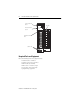
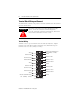
SLC 500™ RTD/Resistance Input Module Channel Status LEDs (Green) Module Status LED (Green) INPUT CHANNEL STATUS 0 1 2 3 Door Label MODULE STATUS RTD/resistance SHIELD CHL 0 RTD Removable Terminal Block CHL 0 SENSE SHIELD CHL 1 RT D CHL 1 CHL 0 SENSE RETRN CHL 1 RETRN SHIELD SHIELD CHL 2 RTD CHL 2 SENSE CHL 2 RETRN Cable Tie Slots Required Tools and Equipment Have the following tools and equipment ready • • • • • • medium blade screwdriver medium cross-head screwdriver RTD module (1746-NR4)
SLC 500™ RTD/Resistance Input Module 5 Electrostatic Damage Electrostatic discharge can damage semiconductor devices inside this module if you touch backplane connector pins or other sensitive areas. Guard against electrostatic damage by observing the following precautions. ATTENTION Electrostatic discharge can degrade performance or cause permanent damage. Handle the module as stated below. ! • Wear an approved wrist strap grounding device when handling the module.
SLC 500™ RTD/Resistance Input Module Fixed Expansion Chassis Considerations IMPORTANT The 2-slot, SLC 500 fixed I/O expansion chassis (1746-A2) supports many combinations of modules. The combinations that are not supported by the fixed expansion chassis are shown in the table below.
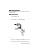
SLC 500™ RTD/Resistance Input Module 7 Module Installation and Removal When installing the module in a chassis, it is not necessary to remove the terminal block from the module. Module Installation Procedure 1. Align the circuit board of the RTD module with the card guides located at the top and bottom of the chassis. 2. Slide the module into the chassis until both top and bottom retaining clips are secured. Apply firm even pressure on the module to attach it to its backplane connector.
SLC 500™ RTD/Resistance Input Module Terminal Block Wiring and Removal The RTD module contains an 18-position, removable terminal block. The terminal pin-out is shown below. ATTENTION ! Disconnect power to the SLC before attempting to install, remove, or wire the removable terminal wiring block. To avoid cracking the removable terminal block, alternate the removal of the terminal block release screws. Terminal Wiring Terminal screws accept a maximum of two #14 AWG (2 mm2) wires.
SLC 500™ RTD/Resistance Input Module 9 Terminal Block Removal If the terminal block is removed, use the write-on label located on the side of the terminal block to identify the module location and type. To remove the terminal block: 1. Loosen the two terminal block release screws. 2. Grasp the terminal block at the top and bottom and pull outward and down. Wiring Considerations Follow the guidelines below when planning your system wiring.
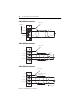
SLC 500™ RTD/Resistance Input Module 2-Wire RTD Interconnection Cable Shield Add Jumper Shield CH 0 RTD RTD RTD Return Return CH 0 Sense CH 0 Return Belden #9501 Shielded Cable 3-Wire RTD Interconnection Cable Shield Shield CH 0 RTD RTD RTD Sense Sense Return Return CH 0 Sense CH 0 Return Belden #9501 or #9533 Shielded Cable 4-Wire RTD Interconnection Cable Shield Shield CH 0 RTD CH 0 Sense CH 0 Return Belden #9501 or #9533 Shielded Cable RTD RTD Sense Sense Return Return Belden
SLC 500™ RTD/Resistance Input Module IMPORTANT 11 The RTD module requires three wires to compensate for lead resistance error. We recommend that you do not use 2-wire RTDs if long cable runs are required, as it will reduce the accuracy of the system. However, if a 2-wire configuration is required, reduce the effect of the lead wire resistance by using a lower gauge wire for the cable (for example, use AWG #16 instead of AWG #24). Also, use cable that has a lower resistance per foot of wire.
SLC 500™ RTD/Resistance Input Module There are several ways to insure that the lead values match as closely as possible. They are as follows: • Keep lead resistance as small as possible and less than 25Ω. • Use quality cable that has a small tolerance impedance rating. • Use a heavy-gauge lead wire which has less resistance per foot. Wiring Resistance Devices (Potentiometers) to the NR4 Module Potentiometer wiring requires the same type of cable as that for the RTD described on page 9.
SLC 500™ RTD/Resistance Input Module 13 3-Wire Potentiometer Interconnection Cable Shield Run RTD and sense wires from module to potentiometer terminal and tie them to one point. Shield CH 0 RTD CH 0 Sense CH 0 Return Potentiometer RTD Sense Return Belden #9501 or #9533 Shielded Cable Cable Shield Run RTD and sense wires from module to potentiometer terminal and tie them to one point.
SLC 500™ RTD/Resistance Input Module Wiring Input Devices to the NR4 Module 2-Conductor Shielded Cable (See Step 4.) Signal Wire Signal Wire Signal Wire (See step 3.) Foil Shield Drain Wire Signal Wire 3-Conductor Shielded Cable (See Step 4.) Signal Wire Signal Wire (See step 3.) Signal Wire Drain Wire Foil Shield Signal Wire Signal Wire Signal Wire To wire your NR4 module, follow these steps. 1. At each end of the cable, strip some casing to expose the individual wires. 2.
SLC 500™ RTD/Resistance Input Module 15 Module Addressing The following memory map of shows you how the output and input image tables are defined for the RTD module. Bit 15 SLC 5/0X Data Files Slot e RTD Module Image Table Output Scan Output Image 8 Words Output Image Slot e Input Image Bit 0 Address O:e.0 Channel 0 Configuration Word Word 0 Channel 1 Configuration Word Word 1 O:e.1 Channel 2 Configuration Word Word 2 O:e.2 Channel 3 Configuration Word Word 3 O:e.
SLC 500™ RTD/Resistance Input Module Channel Configuration Once the module is installed, each channel can be configured to establish the way the channel will operate. You configure the channel by entering bit values into the configuration word using your programming software. Channels 0 through 3 on the NR4 are configured by entering bit values into output words 0 through 3 respectively.
SLC 500™ RTD/Resistance Input Module Make these bit settings 15 14 13 12 11 10 9 8 7 6 5 0 0 0 1 1 0 1 1 Enable 1 Disable 0 2.0 mA Scaling Enable Channel 10 Hz 50 Hz 60 Hz 250Hz Excitation Current Filter Frequency To Select (1) (2) (3) (4) (5) (6) 3 2 1 0 0 0.5 mA 1 Default 0 0 User-set (Range 0)(6) 0 1 User-set (Range 1)(6) 1 0 Invalid 1 1 Unused 4 17 0 Actual value at 0°C is 9.042Ω per SAMA standard RC21-4-1966. Actual value at 0°C is 100Ω per DIN standard.
SLC 500™ RTD/Resistance Input Module Specifications Electrical Specifications Backplane Current Consumption 50 mA at 5V dc 50 mA at 24V dc Backplane Power Consumption 1.5W maximum (0.3 W at 5V dc, 1.
SLC 500™ RTD/Resistance Input Module 19 Physical Specifications LED Indicators 5 green status indicators, one for each of 4 channels and one for module status Module ID Code 3513 Maximum Termination Wire Size Two 14 AWG wire per terminal Maximum Cable Impedance 25 ohms maximum impedance for 3-wire RTD configuration (see Cable Specifications) Terminal Block Removable, Allen-Bradley spare part Cat. No.
SLC 500™ RTD/Resistance Input Module Input Specifications RTD Types platinum, nickel, nickel iron, copper (For additional information on RTD types, see page 21.) Temperature Scale (Selectable) °C or °F and 0.1°C or 0.1°F Resistance Scale (Selectable) 1Ω or 0.1Ω for all resistance ranges; or 0.1Ω or 0.01Ω for 150Ω potentiometer. Input Step Response Refer to the SLC 500™ RTD/Resistance Input Module User Manual , 1746-6.7.
SLC 500™ RTD/Resistance Input Module 21 RTD Temperature Ranges, Resolution, and Repeatability RTD Type Temp. Range (0.5 mA Excitation)(4) Temp. Range (2.0 mA Excitation) Resolution Repeatability 100Ω -200 °C to +850 °C (-328 °F to +1562 °F) -200 °C to +850 °C (-328 °F to +1562 °F) 0.1 °C (0.2 °F) ±0.2 °C (± 0.4 °F) 200Ω -200 °C to +850 °C (-328 °F to +1562 °F) -200 °C to +850 °C (-328 °F to +1562 °F) 0.1 °C (0.2 °F) ± 0.2 °C (± 0.
SLC 500™ RTD/Resistance Input Module RTD Accuracy and Temperature Drift Specifications Accuracy(4) (0.5 mA Excitation) Accuracy(4) (2.0 mA Excitation) Temperature Drift(6) (0.5 mA Excitation) Temperature Drift(6) (2.0 mA Excitation) 100Ω ± 1.0 °C (±2.0 °F) ± 0.5 °C (± 0.9 °F) ± 0.034 °C/°C (± 0.061 °F/°F) ± 0.014 °C/°C (± 0.025 °F/°F) 200Ω ± 1.0 °C (± 2.0 °F) ± 0.5 °C (± 0.9 °F) ± 0.034 °C/°C (± 0.061 °F/°F) ± 0.014 °C/°C (± 0.025 °F/°F) 500Ω ± 0.6 °C (± 1.1 °F) ± 0.5 °C (± 0.
SLC 500™ RTD/Resistance Input Module IMPORTANT 23 Module accuracy, using 100Ω or 200Ω platinum RTDs with 0.5 mA excitation current, depends on the following criteria: • Module accuracy is ± 0.6°C after you apply power to the module or perform an autocalibration at 25°C ambient with module operating temperature at 25°C. • Module accuracy is ± (0.6°C + DT x 0.034°C/°C) after you apply power to the module or perform an autocalibration at 25°C ambient with the module operating temperature between 0° to 60°C.
For More Information For Refer to this Document Pub. No. A more detailed description on how to install and use your RTD/Resistance Input Module. SLC 500 RTD/Resistance Input Module User Manual 1746-6.7 A more detailed description on how to install and use your modular SLC 500 system. SLC 500 Module Hardware Style User Manual 1747-6.2 A more detailed description on how to install and use your fixed SLC 500 system. SLC 500 Fixed Hardware Style Installation and Operation Manual 1747-6.