SLC 500 8-Channel Analog Output Modules 1746-NO8I and 1746-NO8V User Manual
Important User Information Because of the variety of uses for the products described in this publication, those responsible for the application and use of these products must satisfy themselves that all necessary steps have been taken to assure that each application and use meets all performance and safety requirements, including any applicable laws, regulations, codes and standards.
Table of Contents Preface Who Should Use this Manual. . . . . . . . . . Purpose of this Manual . . . . . . . . . . . . . . Common Techniques Used in this Manual Related Documentation . . . . . . . . . . . . . . . . . . . . . . . . . . . . . . . . . . . . . . . . . . . . . . . . . . . . . . . . . . . . . . . . . . P-1 P-1 P-1 P-2 Chapter 1 Overview What the Module Does . . . . . . . . . . . . . . . . . . . . . . . . . . . 1-1 General Features And Benefits . . . . . . . . . . . . . . . . . .
Table of Contents ii Chapter 4 Configuring the Module Entering the Module ID Code . . . . . . . . . . . . . . . . Configuring the Module Using RSLogix 500 . . . . . . Configuring Each Output Channel . . . . . . . . . . . . . Class 1 and Class 3 Configuration . . . . . . . . . . . Class 3 Configuration . . . . . . . . . . . . . . . . . . . . Configuration Options . . . . . . . . . . . . . . . . . . . Setting the Parameter Option Values (Class 3 Only) Ladder Program to Configure Channel 0. . . . . . . . .
Preface Read this preface to familiarize yourself with the rest of the manual. It provides information concerning: • • • • • Who Should Use this Manual who should use this manual the purpose of this manual related documentation conventions used in this manual Rockwell Automation support Use this manual if you are responsible for designing, installing, programming, or troubleshooting automation control systems that use Allen-Bradley small logic controllers.
Preface 2 Related Documentation The following documents contain information that may be helpful to you as you use Allen-Bradley SLC products. If you would like a manual, you can: • download a free electronic version from the internet: • www.theautomationbookstore.com • purchase a printed manual by: – contacting your local distributor or Rockwell Automation representative – visiting www.theautomationbookstore.com and placing your order – calling 1.800.963.9548 (USA/Canada) – or 001.330.725.
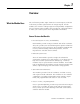
Chapter 1 Overview What the Module Does The 1746-NO8I provides eight channels of current outputs, while the 1746-NO8V provides eight channels of voltage outputs. In both modules, the current or voltage ranges are independently configurable for each channel. These modules also provide new, advanced features to make your control systems more dependable and flexible. General Features And Benefits • Increased System Accuracy and Reliability Both modules provide 8 output channels with 16-bit resolution.
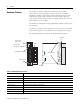
1-2 Overview Hardware Features The module contains a removable terminal block, providing connection for 8 analog output channels, which are specifically designed to interface with analog current and voltage devices. The 1746-NO8I provides eight channels of current outputs, while the 1746-NO8V provides eight channels of voltage outputs. There are no input channels on the module. The module is configured via the programming software. There are no DIP switches.
Chapter 2 Installation and Wiring This chapter tells you how to: • avoid electrostatic damage • determine the chassis power requirement for the module • use an external 24V dc power supply (optional) • choose a location for the module in the SLC chassis • install and remove the module • wire the module’s terminal block • label and re-install the terminal block Compliance to European Union Directives This product is approved for installation within the European Union and EEA regions.
2-2 Installation and Wiring Low Voltage Directive This product is tested to meet Council Directive 73/23/EEC Low Voltage, by applying the safety requirements of EN 61131-2 Programmable Controllers, Part 2 – Equipment Requirements and Tests. For specific information required by EN61131-2, see the appropriate sections in this publication, as well as the following Allen-Bradley publications: • Industrial Automation, Wiring and Grounding Guidelines for Noise Immunity, publication 1770-4.
Installation and Wiring Avoiding Electrostatic Damage 2-3 Electrostatic discharge can damage semiconductor devices inside this module if you touch backplane connector pins. Guard against electrostatic damage by observing the following precautions. ATTENTION ! Electrostatic discharge can degrade performance or cause permanent damage. Handle the module as stated below. • Wear an approved wrist strap grounding device when handling the module.
2-4 Installation and Wiring Using an External 24V dc Power Supply (optional) The module has an external 24 V dc power jumper, J4, giving you the option of using an external power supply. Setting The Jumper J4 The jumper, J4, is located in the bottom right corner of the module’s circuit board next to the power supply as shown below: J4 jumper location EXT 1 2 3 RACK • With the jumper in the 1-2 Shorted position, the module draws all of its power from the backplane of the SLC system.
Installation and Wiring 2-5 Important Notes about Using an External 24V dc Power Supply ATTENTION ! IMPORTANT Before setting the jumper, all system power must be turned off. This includes the rack power as well as any external 24V dc power supply. If the module is configured to use an external 24V dc power supply, the supply must be turned on for the module to operate.
2-6 Installation and Wiring Choosing a Slot Location in the Chassis When selecting a slot for the module, consider the following conditions: Table 2.2 Conditions for Locating the Analog Module Condition Recommendation SLC chassis slot 0 is reserved Place the module in any slot of an SLC 500 modular, or modular expansion chassis, except for the extreme left slot (slot 0) in the first chassis. This slot is reserved for the processor or adapter module.
Installation and Wiring Module Installation and Removal 2-7 The printed circuit boards of the analog module must be protected from dirt, oil, moisture and other airborne contaminants. To protect these boards, the SLC 500 system must be installed in an enclosure suitable for the environment. The interior of the enclosure should be kept clean and the enclosure door should be kept closed whenever possible. ATTENTION ! Remove power before removing or inserting the module.
2-8 Installation and Wiring Module Installation Procedure 1. Read “Choosing a Slot Location in the Chassis” beginning on page 2-6. 2. Align the circuit board of the analog input module with the card guides located at the top and bottom of the chassis. 3. Slide the module into the chassis until both top and bottom retaining clips are secured. Apply firm, even pressure on the module to attach it to its backplane connector. Never force the module into the slot. 4.
Installation and Wiring Wiring the Module 2-9 To wire the terminal block, you need: • cross-head and flat-blade screwdrivers • Belden 8761 (shielded, twisted pair) cable or equivalent Each terminal may hold up to two 14 gauge leads. ATTENTION ! POSSIBLE EQUIPMENT OPERATION Before wiring your module, always disconnect power from the SLC 500 system and from any other source to the module. Failure to observe this precaution can cause unintended equipment operation and damage.
2-10 Installation and Wiring Wiring Procedure To wire your module, follow these steps: 1. Determine the length of cable you need to connect a channel to its field device. Remember to include additional cable to route the shield wire and foil shield to their ground points. 2. At each end of the cable, strip some casing to expose the individual wires. 3. Trim the exposed signal wires to 50 mm (2 in) lengths. Strip about 5 mm (3/16 in.) of insulation away to expose the end of each wire. 4.
Installation and Wiring 2-11 Terminal Block The 1746-NO8 module contains an 18-position, removable terminal block. The terminal pin-out is shown below. ATTENTION ! Disconnect power to the SLC before attempting to install, remove, or wire the removable terminal wiring block. To avoid cracking the removable terminal block, alternate the removal of the slotted terminal block release screws. Figure 2.
2-12 Installation and Wiring A system may malfunction due to a change in its operating environment. After installing and wiring your module, check system operation. See your controller’s User Manual for more information. Labeling and Re-Installing the Terminal Block (if it is removed) The supplied terminal cover has a write-on label. Using this label helps ensure that the terminal block is installed on the correct module.
Chapter 3 Preliminary Operating Considerations This chapter explains how the analog output module and the SLC 500 processor communicate through the module’s input and output image. It lists the preliminary setup and operation required before the module can function in a 1746 I/O system.
3-2 Preliminary Operating Considerations Class 1 and Class 3 Operation The 1746-NO8 analog output modules have multi-class interface capabilities. Class 1 is the default configuration. The modules can be configured through the user program for Class 3, which enables user-defined data scaling and monitoring of channel status words. Use Class 3 operation whenever possible. Table 3.
Preliminary Operating Considerations How the SLC Processor Communicates with the Module 3-3 The SLC processor transfers data to (and receives data from) the output module through an image table residing in the data files of the SLC processor. The processor updates this image table once during each scan of the ladder program. Figure 4 shows the image table for your output module. Figure 3.
3-4 Preliminary Operating Considerations Module Response to Slot Disabling By writing to the status file in the modular SLC processor, you can disable any chassis slot. Refer to the SLC 500 Instruction Set Reference Manual, publication 1747-RM001, for the slot disable/enable procedure. ATTENTION ! POSSIBLE EQUIPMENT OPERATION Always understand the implications of disabling a module before using the slot disable feature.
Chapter 4 Configuring the Module Read • • • this chapter to: enter the output module’s ID code configure the module using the RSLogix 500 wizard configure the module using output words (includes detailed description of all configuration options and examples) • set the optional features (user scaling, clamping, limit alarm, ramping/rate limit, and preset fault value) • review an example ladder program to configure Channel 0 To configure the module, you need: • programming equipment • RSLogix 500 programm
4-2 Configuring the Module Configuring the Module Using RSLogix 500 RSLogix 500 version 6.10 (and later) includes an advanced configuration wizard to assist in configuring the 1746-NO8 module when Class 3 mode is used. 1. To bring up the I/O Configuration interface, double-click on the I/O Configuration icon. 2. Assign the 1746-NO8 to a chassis slot and select Class 3 operation.
Configuring the Module 4-3 3. Highlight the module and clicking on the “Adv Config” button to open the “Advanced I/O Configuration” interface for the 1746-NO8. 4. From the “Advanced I/O Configuration” interface, click the “Configure” button to open the 1746-NO8 configuration interface. 5. The interface for the 1746-NO8 includes eight identical configuration tabs; one tab for each channel.
4-4 Configuring the Module 6. Check boxes and pull-downs allow for complete configuration for each channel. The pull-downs provide the following configuration options: a. The “Channel Enabled” check box controls bit 0 of the channel configuration word. b. The “Output Type” pull-down allows configuration of the output range (bits 1 and 2 of the channel configuration word), dependent upon the module being used.
Configuring the Module 4-5 d. The “Options” pull-down allows selection of the data format (bits 4 to 6 of the channel configuration word): Options: 1746-NO4 Data Format Engineering Units Scaled for PID Proportional Counts User-defined e. “Latch Alarms” and “Reset Latched Alarms” check boxes allow channel configuration word bits 14 and 15 to be configured. f. The “Fault Options” pull-down allows channel configuration fault options to be selected (bits 12 and 13 of the channel configuration word).
4-6 Configuring the Module Configuring Each Output Channel Class 1 and Class 3 Configuration Output words 0 through 7 (addresses O:e.0 through O:e.7) hold the output data for channels 0 through 7 respectively. Class 3 Configuration After installing the module, you must configure each channel by setting bit values in each configuration word. Output words 8 through 15 (addresses O:e.8 through O:e.15) configure channels 0 through 7 respectively. Figure 4.1 1746-NO8 Output Addressing O:e.
Configuring the Module 4-7 Configuration Options Table 4.
4-8 Configuring the Module Data Format (configuration bits 4 to 6) Use this bit field to select one of the following formats: • 1746-NO4 compatible format (the format used by the 1746-NO4) • engineering units (mV or nA) • scaled for PID (works with the SLC PID instruction) • proportional counts (two’s complement binary) • user-defined scale These data formats and ranges are defined in the following table: Table 4.
Configuring the Module 4-9 Parameter Set or Clear (configuration bits 7 and 8) These bits are used to load the values from Data Parameters 1 and 2 into the corresponding feature. Setting these values also enables most features. If bit 7 is set (1), then the Data Parameter is cleared. If bit 8 is set (1), the Data Parameter is set for the feature. A configuration error occurs if both are set to 1 at the same time.
4-10 Configuring the Module IMPORTANT The values in output word pairs 16 through 31 apply to each individual channel. If you want to use any of these features, you must set each channel’s output word pair. Changing the output data format or range (bits 1 to 6 of the channel configuration word) will clear or disable user-scaling, clamping, limit alarms, ramping/rate limiting and preset fault values. Similarly, if format or range is changed, you must reconfigure the values for each of these features.
Configuring the Module 4-11 Fault conditions are listed below: • CPU Fault • Rack power goes away while the external 24V power remains When the rack power is restored, the channel outputs will go to the reset power state during power-up self test. After this, the channels will output their commanded values if enabled with a valid configuration.
4-12 Configuring the Module Setting the Parameter Option Values (Class 3 Only) TIP Once the Data Parameters have valid values and bits 9 to 11 are set; then set bit 8 (set optional feature) to set the feature, or set bit 7 (clear optional feature) to clear the feature. User-Defined Scale For special applications, the module allows definition of a custom data format.
Configuring the Module 4-13 Now set the bits in the Channel 0 configuration word to define the user-scaling values. Address O:e.8 15 0 0 0 0 Channel 0 Configuration Word 0 0 1 1 0 1 0 0 0 0 1 0 1 Monitor bit 0 of Channel 0 Input Status Word 2 (I:e.8). When this bit is 1 (user scaling values set), then set the Channel 0 configuration to be User-Scaling. Address O:e.
4-14 Configuring the Module The low clamp limit value must be lower than the high clamp limit value. For some ranges and formats, the clamp alarms will occur a few counts from the set clamping values. This means you may need to command an output value lower or higher than the output clamping limits in order to get output at low/high clamp alarms.
Configuring the Module 4-15 Figure 4.4 Output Clamping Example Data Output 10V 8V 2V -10V -10,000 -210,000 +8,000 +10,000 Note that whenever the requested output data values meet or attempt to exceed the output data limits, the module sets bits 9 or 10 in Input Status Word 2 (I:e.8 for Channel 0) to indicate a clamp alarm.
4-16 Configuring the Module Address O:e.14 15 0 0 0 0 0 Channel 6 Configuration Word 0 0 0 0 0 0 0 0 1 0 0 1 Suppose, also, that you would like to provide an alarm if the output data word was commanded to less than 100 counts and greater than 30,000 counts. You would enter the following for Channel 6 data parameters 1 and 2. O:e.22 Value = 100 decimal O:e.30 Value = 30000 decimal Now set the bits in the Channel 6 configuration word. Address O:e.
Configuring the Module 4-17 EXAMPLE 4: Set Ramping/Rate Limit Values Suppose you have a valve connected to Channel 4 with a 4 to 20 mA operating range and you want to use PID format. You would use the following bit settings for the Channel 4 configuration word: Address O:e.12 15 0 0 0 0 Channel 4 Configuration Word 0 0 0 0 0 0 1 0 0 0 1 0 1 Suppose, also, that you would like the output to change no more than 1.5 mA per second. Since the ramping value is expressed as 0.
4-18 Configuring the Module EXAMPLE 5: Set Preset Fault Values Suppose you have a valve connected to Channel 7 with a 4 to 20 mA operating range and you want to use Engineering Units format. You would use the following bit settings for the Channel 7 configuration word: Address O:e.15 15 0 0 0 0 Channel 7 Configuration Word 0 0 0 0 0 0 0 1 0 0 1 0 1 Suppose, also, that you would like the output to go to 12 mA if a fault condition occurred.
Configuring the Module 4-19 Ladder Program to Configure Channel 0 The rung below configures Channel 0 for 0 to 21 mA, sets the clamping range from 4000 to 20000, and holds the output in its last state on a fault condition. Note: 5393 decimal = 0001 0101 0001 0001 binary. CH0_CLAMPING_SET 0000 I:1.8 ]/[ 1 OTHER CH0_PARAMETER1 MOV MOVE Source Dest 4000 4000 < O:1.16 5000 < CH0_PARAMETER2 MOV MOVE Source Dest 20000 20000 < O:1.24 10000 < CH0_CONFIG MOV MOVE Source Dest 5393 5393 < 0:1.
4-20 Configuring the Module The rung below configures Channel 0 for 0 to 21 mA, sets the alarm limit range from 5000 to 10000, and holds the output in its last state on a fault condition. Note: 5905 decimal = 0001 0111 0001 0001 binary. CH0_CLAMPING_SET I:1.8 ] [ 1 OTHER 0001 CH0_LIMIT_AL_SET I:1.8 ]/[ 2 OTHER CH0_PARAMETER1 MOV MOVE Source Dest 5000 5000 < O:1.16 5000 < CH0_PARAMETER2 MOV MOVE Source Dest 10000 10000 < O:1.24 10000 < CH0_CONFIG MOV MOVE Source Dest 5905 5905 < 0:1.
Chapter 5 I/O Data and Status Information Read this chapter to: • monitor each output channel • check each channel’s configuration and status Output Image and Input Image Overview Output Image The output image (defined as the output from the SLC processor to the module) defines how each channel on your module works. Table 5.1 1746-NO8 Output Image Operation Operating Mode Output Image Size Module Operation Class 1 8-word The output data words control the output signal level for each channel.
5-2 I/O Data and Status Information The output image is shown in the following figure. Figure 5.1 1746-NO8 Output Image O:e.1 Channel 1 Channel 6 O:e.7 Channel 7 O:e.8 Channel 0 O:e.9 Channel 1 … O:e.6 Channel 6 O:e.15 Channel 7 O:e.16 Channel 0 O:e.17 Channel 1 … O:e.14 Channel 6 O:e.23 Channel 7 O:e.24 Channel 0 O:e.25 Channel 1 … O:e.22 O:e.30 Channel 6 O:e.
I/O Data and Status Information 5-3 Input Image The input image (defined as the input from the module to the SLC processor) provides information to determine various channel conditions. Table 5.2 1746-NO8 Input Image Operation Operating Mode Input Image Size Module Operation Class 1 8-word The input data words hold the data received by your module and provide the status (configuration and operational state) of each channel.
5-4 I/O Data and Status Information Input Status Words Channel Input Status Word 1 (Class 1 and Class 3) Words 0 through 7 of the input image file (addresses I:e.0 through I:e.7) reflect the configuration and status of each channel. Use the data provided in these status words to determine various channel conditions. Input Status 1 addressing and bit definitions are shown in the following figures: Figure 5.3 Input Status 1 I:e.0 Channel 0 I:e.1 Channel 1 Function … Input Status 1 I:e.
I/O Data and Status Information 5-5 Input Status 1 Descriptions Output Enable Echo (Status Bit 0) This bit shows the current channel status. The channel is enabled when this bit echo is 1. Output Range Echo (Status Bits 1 and 2) These bits echo the current output range for the active channel.
5-6 I/O Data and Status Information Channel Input Status Word 2 (Class 3 Only) Words 8 through 15 of the input image file (addresses I:e.8 through I:e.15) reflect the parameter options, fault settings, and alarm options for each channel. Input Status 2 addressing and bit definitions are shown in the following figures: Figure 5.4 Input Status 2 I:e.8 Channel 0 I:e.9 Channel 1 Function … Input Status 2 I:e.14 Channel 6 I:e.15 Channel 7 Class 3 Input Image Words 0 through 7 Table 5.
I/O Data and Status Information 5-7 Input Status 2 Descriptions User Scaling Values Set (Status Bit 0) This bit indicates that user scaling values have been set for this channel. If the channel format is user scaling and the channel is enabled, user scaling is active. Clamping Values Set (Status Bit 1) This bit indicates that clamping values have been set for the channel. If the channel is enabled, then clamping is active.
5-8 I/O Data and Status Information Alarms Will Be Latched (Status Bit 8) This bit indicates that the channel alarms will latch if an error occurs. When this bit is set and an alarm condition occurs, the Alarm Status bit will stay set until you reset the bit using the Reset Latched Alarms bit. Output At Low Clamp Alarm (Status Bit 9) This bit indicates that the channel output data value is being commanded to go below the user defined low clamp value.
Chapter 6 Module Diagnostics and Troubleshooting Read • • • • • • this chapter to prevent potential problems. This chapter covers: inspecting your module disconnecting prime movers power-up diagnostics interpreting the LED indicators interpreting I/O error codes troubleshooting Before testing your module, test your SLC 500 system using the procedures described in your controller’s User Manual.
6-2 Module Diagnostics and Troubleshooting Disconnecting Prime Movers Before testing your module, ensure that machine motion will not occur: • Disconnect motor wires at the motor starter or the motor itself. This allows you to test the operation of the starter coil, verifying that the output circuit is wired correctly and functioning. • Disconnect solenoids by disengaging the solenoid valves, leaving the coils connected.
Module Diagnostics and Troubleshooting 6-3 The module has 9 LEDs: • 8 channel status LEDs (for Channels 0 through 7) • 1 module status LED Interpreting the LED Indicators Figure 6.1 Module LEDs OUTPUT CHANNEL STATUS MODULE 0 4 1 5 2 6 3 7 ANALOG Use the following table to interpret the LEDs: Table 6.1 1746-NO8 LED Indications Module LED Status Channel LED Status Indicates On solid On solid The channel is enabled. On solid On flashing, 1-flash sequence Open circuit.
6-4 Module Diagnostics and Troubleshooting Interpreting I/O Error Codes I/O error codes appear in word S:6 of the SLC 500 processor status file. The first two digits of the error code identify the slot (in hexadecimal) experiencing the error. The last two digits identify the I/O error code (in hexadecimal).
Module Diagnostics and Troubleshooting Troubleshooting 6-5 Figure 6.2 Problem Resolution Flowchart Check LEDs on module. Module Status LED off. Module fault condition. Check that module is properly seated in chassis. Cycle power. Module Status LED flashing. Module Status LED on. 1 Flash 24V Power Failure Check external supply or jumper settings (if used). 2 Flashes Configuration Error Check module and channel configuration settings. 3 Flashes Channel Status LED(s) flashing.
6-6 Module Diagnostics and Troubleshooting Publication 1746-UM026A-EN-P - September 2003
Chapter 7 Maintenance and Safety Read this chapter to familiarize yourself with: • preventive maintenance • safety considerations Preventative Maintenance The printed circuit boards of the analog modules must be protected from dirt, oil, moisture and other airborne contaminants. To protect these boards, install the SLC 500 system in an enclosure suitable for its operating environment. Keep the interior of the enclosure clean, and whenever possible, keep the enclosure door closed.
7-2 Maintenance and Safety The following section describes several safety areas you should be aware of when troubleshooting your SLC 500 system. Indicator Lights — When the module status LED on the module is illuminated, the module is receiving power. Activating Devices When Troubleshooting — When troubleshooting, never reach into the machine to actuate a device. Unexpected machine motion could occur. Use a wooden stick.
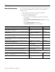
Appendix A Specifications Table A.1 General Specifications Specification 1746-NO8I I/O Chassis Location Any 1746 chassis slot except slot 0 Backplane Current Consumption (maximum) 120 mA at 5V dc 120 mA at 5V dc 250 mA at 24V dc (J4 jumper set to RACK) 0 mA at 24V dc (J4 jumper set to EXT) 160 mA at 24V dc (J4 jumper set to RACK) 0 mA at 24V dc (J4 jumper set to EXT) Backplane Power Consumption (typical) 5.6W Optional External 24V dc Power Supply +24V dc +/-10% (N.E.C.
A-2 Specifications Table A.2 Analog Output Specifications Specification 1746-NO8I 1746-NO8V Number of Outputs 8 8 Output Type Current Voltage Output Range 0 to 21.5 mA ±10.25V dc Output Coding (proportional scaling) 0 to 32,767 -32,768 to +32,767 Output D/A Converter Resolution 16-bit 16-bit 366 nA/count 320 µV/count Location of LSB in I/O Image Word 0000 0000 0000 0001 (for 1746-NO4 compatible data format; does not apply to other data formats) Non-Linearity 0.
Specifications A-3 Table A.3 Configuration and Status Specifications Specification 1746-NO8I 1746-NO8V Module ID Code Class 1: 3527 Class 1: 3528 Class 3: 12727 Class 3: 12728 8 8 Number of Output Channels • 4 to 20 mA Current Output Ranges n/a • 0 to 20 mA (selectable for each channel) • 0 to 21 mA • 0 to 21.5 mA Voltage Output Ranges • -10 to +10V dc n/a • -10.25 to +10.
A-4 Specifications Table A.4 Environmental Specifications Specification 1746-NO8I 1746-NO8V Operating Temperature 0°C to +60°C (+32°F to +140°F) Storage Temperature -40°C to +85°C (-40°F to +185°F) Operating Humidity 5 to 95% non-condensing Vibration Operating: 5.0G at 10 to 500Hz, One Octave/min sweep, 10 sweeps Shock Operating: 30G (3 pulses, 11 ms) Non-Operating: 50G (3 pulses, 11 ms) Free Fall (drop test) Portable, 2.268 kg (5 lbs) or less at 0.762m (30 in.) (six drops) Portable, 2.
Appendix B Replacing 1746-NO4s with 1746-NO8 Converting from 1746-NO4 to 1746-NO8 This information is provided for those who are replacing two 1746-NO4 modules with one 1746-NO8 module. When using the 1746-NO8 module in Class 1 mode, no changes to the user program are required, except that the addressing will change when using one 1746-NO8 to replace two 1746-NO4 modules (see addressing example that follows). Additional status feedback is also available, and monitoring logic may be added if desired.
B-2 Replacing 1746-NO4s with 1746-NO8 Module Addressing Addressing is changed from two modules with 4 channels to one module with 8 channels. The output addressing is shown below. N N O O 4 4 SLOT 0 1 2 3 4 5 3 • • • • O:4.0 - Slot 4, Channel 0 Data Word O:4.1 - Slot 4, Channel 1 Data Word O:4.2 - Slot 4, Channel 2 Data Word O:4.3 - Slot 4, Channel 3 Data Word 1746-NO8 Output Addressing • O:3.0 - Slot 3, Channel 0 Data Word • O:3.1 - Slot 3, Channel 1 Data Word • O:3.
Replacing 1746-NO4s with 1746-NO8 B-3 Table B.3 1746-NO8V and 1746-NO4V Output Range Voltage Range Decimal Representation for Output Word Resolution per LSB -10 to +10V dc -32,768 to +32,764 1.22070 mV 0 to 10V dc 0 to 32,764 0 to 5V dc 0 to 16,384 1 to 5V dc 3,277 to 16,384 Channel Status Words In Class 1 mode, the 1746-NO8 provides one status input word per channel which is not available with the 1746-NO4.
B-4 Replacing 1746-NO4s with 1746-NO8 Publication 1746-UM026A-EN-P - September 2003
Glossary You should understand the following terms and abbreviations before using this guide. For the definitions of terms not listed here, refer to Allen-Bradley Industrial Automation Glossary, publication AG-7.1 1 Channel Refers to one of the sets of signal interfaces available on a module’s terminal block. Channel update time For analog outputs, the time required for the channel to convert the data received from the processor to analog output signals at the terminals.
Glossary 2 Publication 1746-UM026A-EN-P - September 2003 Repeatability The closeness of agreement among repeated measurements of the same variable under the same conditions. Resolution The smallest detectable change in a measurement, typically expressed in engineering units (e.g. microseconds) or as a number of bits. For example, a 16-bit system has 65536 possible output states. It can therefore measure 1 part in 65536. See also effective resolution.
Index Numerics 1747-ACN(R)15 3-2 1747-ASB 3-2 A A.I.
ii Index publications, related P-2 purpose of this manual P-1 R related publications P-2 remote chassis 3-2 removable terminal block 1-2 RSLogix 500 3-2 S safety 7-1 safety circuits 7-2 self-locking tabs 1-2 shield connections 2-11 slot location 2-6 software 3-2 Publication 1746-UM026A-EN-P - September 2003 T terminal block labeling and re-installing 2-12 layout 2-11 removal 2-7 testing your module 6-2 troubleshooting 6-1, 6-5, 7-1, 7-2 U update time 3-3 W wiring 2-1 guidelines 2-9 procedure 2-10 ro
Rockwell Automation Support Rockwell Automation provides technical information on the web to assist you in using our products. At http://support.rockwellautomation.com, you can find technical manuals, a knowledge base of FAQs, technical and application notes, sample code and links to software service packs, and a MySupport feature that you can customize to make the best use of these tools.