Installation Instructions SLC 500™ Analog Input Module (Catalog Number 1746-NI8) Inside… Important User Information ........................................................................... 2 For More Information ...................................................................................... 3 Hazardous Location Considerations ............................................................. 4 Environnements dangereux ..........................................................................
SLC 500™ Analog Input Module Important User Information Because of the variety of uses for the products described in this publication, those responsible for the application and use of this control equipment must satisfy themselves that all necessary steps have been taken to assure that each application and use meets all performance and safety requirements, including any applicable laws, regulations, codes and standards.
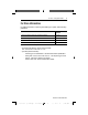
SLC 500™ Analog Input Module 3 For More Information For detailed information on planning and installing your system, see the following publications: Publication Publication Number Industrial Automation Wiring and Grounding Guidelines 1770-4.1 SLC 500™ Analog Input Modules User Manual 1746-6.8 SLC 500™ Modular Hardware Style Operation and Installation Manual 1747-6.2 SLC 500™ Fixed Hardware Style Operation and Installation Manual 1747-6.
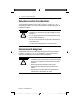
SLC 500™ Analog Input Module Hazardous Location Considerations This equipment is suitable for use in Class I, Division 2, Groups A, B, C, D or non-hazardous locations only. The following WARNING statement applies to use in hazardous locations. WARNING ! EXPLOSION HAZARD • Substitution of components may impair suitability for Class I, Division 2. • Do not replace components or disconnect equipment unless power has been switched off.
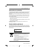
SLC 500™ Analog Input Module 5 Electrostatic Damage Electrostatic discharge can damage semiconductor devices inside this module if you touch backplane connector pins. Guard against electrostatic damage by observing the following precautions. ATTENTION ! Electrostatic discharge can degrade performance or cause permanent damage. Handle the module as stated below. • Wear an approved wrist strap grounding device when handling the module.
SLC 500™ Analog Input Module Module Location in Chassis Modular Chassis Considerations Place your 1746-NI8 module in any slot of an SLC 500 modular, or modular expansion chassis, except for the extreme left slot (slot 0) in the first chassis. This slot is reserved for the processor or adapter modules. IMPORTANT For applications using the upper limit of the operating temperature range, the 1746-NI8 module (or multiple modules) should be placed in the right-most slot(s) of the chassis.
SLC 500™ Analog Input Module 7 Heat and Noise Considerations Most applications require installation in an industrial enclosure to reduce the effects of electrical interference. Analog inputs are highly susceptible to electrical noise. Electrical noise coupled to the analog inputs reduces the performance (accuracy) of the module. Group your modules to minimize adverse effects from radiated electrical noise and heat. Consider the following conditions when selecting a slot for the analog input module.
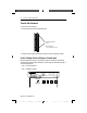
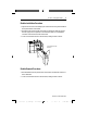
SLC 500™ Analog Input Module Terminal Block Removal To remove the terminal block: 1. Loosen the two terminal block release screws. . Terminal Block Release Screws Maximum Torque = 0.7 to 0.9 Nm (6 to 8 in-lbs) 2. Grasp the terminal block at the top and bottom and pull outward and down. Switch Settings to Select Voltage or Current Input Before installing the module in the chassis, use the DIP switches on the module circuit board to select between voltage and current inputs for channels 0 through 7.
SLC 500™ Analog Input Module 9 Module Installation Procedure 1. Align the circuit board of the analog input module with the card guides located at the top and bottom of the chassis. 2. Slide the module into the chassis until both top and bottom retaining clips are secured. Apply firm even pressure on the module to attach it to its backplane connector. Never force the module into the slot. 3. Cover all unused slots with the Card Slot Filler, catalog number 1746-N2.
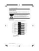
SLC 500™ Analog Input Module Terminal Wiring The 1746-NI8 module contains an 18-position, removable terminal block. The terminal pin-out is shown below. ATTENTION ! Disconnect power to the SLC before attempting to install, remove, or wire the removable terminal wiring block. To avoid cracking the removable terminal block, alternate the removal of the slotted terminal block release screws.
SLC 500™ Analog Input Module 11 Wiring Single-Ended Inputs The following diagram shows typical wiring for the 1746-NI8 module. IMPORTANT Follow these guidelines when wiring the module. • Use shielded communication cable (Belden™ 8761) and keep length as short as possible. • Connect only one end of the cable shield to earth ground. • Connect the shield drain wires for channels 0 to 3 to the top shield terminal.
SLC 500™ Analog Input Module Typical 1746-NI8 Wiring Power Supply Connections + - Shield single-end signal source + + + shield + single-end signal source shield single-end signal source + + + + + + - differential signal source + shield + shield shield + differential signal source Channel 5 + - Channel 4 + + differential signal source Channel 3 - + differential signal source Channel 2 + single-end signal source Channel 1 + shield Channel 0 - Channel 6 shield + shie
SLC 500™ Analog Input Module 13 When wiring single-ended analog input devices to the analog input module, the number of total wires necessary can be limited by jumpering all “IN” terminals together. Note that differential inputs are more immune to noise than single-ended inputs. IMPORTANT The module does not provide loop power for analog inputs. Use a power supply that matches the transmitter specifications.
SLC 500™ Analog Input Module Wiring Schematics for 2, 3, and 4-Wire Analog Input Devices 2-Wire Transmitter Transmitter Power Supply + + - - Module IN + IN - Transmitter 3-Wire Transmitter Supply Module IN + IN - GND Power + Supply- 4-Wire Transmitter Transmitter Supply Signal Power + Supply + - - IMPORTANT + - Module IN + IN - The module does not provide loop power for analog inputs. Use a power supply that matches the transmitter specifications.
SLC 500™ Analog Input Module 15 Wiring Guidelines ATTENTION To prevent shock hazard, care should be taken when wiring the module to analog signal sources. Before wiring any analog module, disconnect power from the SLC 500 system and from any other source to the analog module. ! Follow the guidelines below when planning your system wiring. • To limit noise, keep signal wires as far away as possible from power and load lines.
SLC 500™ Analog Input Module Wiring Input Devices to the 1746-NI8 After the analog input module is properly installed in the chassis, follow the wiring procedure below using Belden 8761 cable. ATTENTION ! Care should be taken to avoid connecting a voltage source to a current input module. Improper module operation or damage to the voltage source can occur. Cable (Cut foil shield and drain wire.
SLC 500™ Analog Input Module 17 Specifications Electrical Specifications Description Specification Backplane Current Consumption 200 mA at 5V dc 100 mA at 24V dc Backplane Power Consumption 3.4W maximum (1.0W at 5V dc, 2.
SLC 500™ Analog Input Module Physical Specifications Description Specification LED Indicators 9 green status indicators one for each of 8 channels and one for module status Module ID Code Class 1 Interface: 3526 Class 3 Interface: 12726 Recommended Cable Belden #8761 or equivalent Maximum Wire Size Two 14 AWG wires per terminal Maximum Cable Impedance Voltage Source (with less than 10Ω impedance): 40Ω maximum loop impedance, for <1LSB error Current Source (transmitter properly wired to its p
SLC 500™ Analog Input Module 19 Input Specifications Description Specification Type of Input (Selectable) ±10V dc 1 to 5V dc 0 to 5V dc 0 to 10V dc 0 to 20 mA 4 to 20 mA ±20 mA 0 to 1 mA Type of Data (Selectable) Engineering Units Scaled-for-PID Proportional Counts (-32,768 to +32,767 range) Proportional Counts (User Defined Range, Class 3 only) 1746-NI4 Data Format Input Impedance 1 MΩ Voltage Input (maximum) ±30V between any two signal terminals Current Input (maximum) 30 mA Time to Detect O
SLC 500 is a trademark of Rockwell Automation. Belden is a trademark of Belden, Inc. Publication 1746-IN006A-US-P - February 2000 PN 40071-081-01 (A) © 2006 Rockwell Automation, Inc. All rights reserved. Printed in Singapore. @ JO " VT Q QE ".