Installation Instructions SLC 500™ Analog Input Modules (Catalog Numbers 1746-NI16I and 1746-NI16V) Inside Important User Information .................................................................... 2 For More Information ................................................................................3 Hazardous Location Considerations ....................................................... 4 Environnements dangereux ....................................................................
SLC 500™ Analog Input Modules Important User Information Because of the variety of uses for the products described in this publication, those responsible for the application and use of this control equipment must satisfy themselves that all necessary steps have been taken to assure that each application and use meets all performance and safety requirements, including any applicable laws, regulations, codes and standards.
SLC 500™ Analog Input Modules 3 For More Information For detailed information on planning and installing your system, see the following publications: Publication Publication Number Industrial Automation Wiring and Grounding Guidelines 1770-4.1 SLC 500™ Analog Input Modules User Manual 1746-UM001A-US-P SLC 500™ Modular Hardware Style Operation and Installation Manual 1747-6.2 SLC 500™ Fixed Hardware Style Operation and Installation Manual 1747-6.
SLC 500™ Analog Input Modules Hazardous Location Considerations This equipment is suitable for use in Class I, Division 2, Groups A, B, C, D or non-hazardous locations only. The following ATTENTION statement applies to use in hazardous locations. WARNING ! EXPLOSION HAZARD • Substitution of components may impair suitability for Class I, Division 2. • Do not replace components or disconnect equipment unless power has been switched off.
SLC 500™ Analog Input Modules 5 Electrostatic Damage Electrostatic discharge can damage semiconductor devices inside this module if you touch backplane connector pins. Guard against electrostatic damage by observing the following precautions. ATTENTION ! Electrostatic discharge can degrade performance or cause permanent damage. Handle the module as stated below. • Wear an approved wrist strap grounding device when handling the module.
SLC 500™ Analog Input Modules Module Location in Chassis Modular Chassis Considerations Place your 1746-NI16 module in any slot of an SLC 500 modular, or modular expansion chassis, except for the extreme left slot (slot 0) in the first chassis. This slot is reserved for the processor or adapter modules.
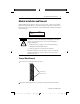
SLC 500™ Analog Input Modules 7 Module Installation and Removal When installing the module in a chassis, it is not necessary to remove the terminal block from the module. However, if the terminal block is removed, use the write-on label (shown below) located on the side of the terminal block to identify the module location and type. SLOT RACK • MODULE ATTENTION Remove power before removing or inserting this module. When ! you remove or insert a module with power applied, an electrical arc may occur.
SLC 500™ Analog Input Modules Module Installation Procedure 1. Align the circuit board of the analog input module with the card guides located at the top and bottom of the chassis. 2. Slide the module into the chassis until both top and bottom retaining clips are secured. Apply firm even pressure on the module to attach it to its backplane connector. Never force the module into the slot. 3. Cover all unused slots with the Card Slot Filler, Catalog Number 1746-N2.
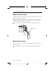
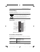
SLC 500™ Analog Input Modules 9 Terminal Wiring The 1746-NI16 module contains an 18-position, removable terminal block. The terminal pin-out is shown below. ATTENTION Disconnect power to the SLC before attempting to install, remove, or wire the removable terminal wiring block. ! To avoid cracking the removable terminal block, alternate the removal of the slotted terminal block release screws.
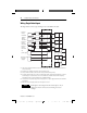
SLC 500™ Analog Input Modules Wiring Single-Ended Inputs The diagram below shows typical wiring for the 1746-NI16V module.
SLC 500™ Analog Input Modules 11 Wiring Single-Ended Inputs The diagram below shows typical wiring for the 1746-NI16I module.
SLC 500™ Analog Input Modules Wiring Guidelines ATTENTION ! To prevent shock hazard, care should be taken when wiring the module to analog signal sources. Before wiring any analog module, disconnect power from the SLC 500 system and from any other source to the analog module. Follow the guidelines below when planning your system wiring. • To limit noise, keep signal wires as far away as possible from power and load lines.
SLC 500™ Analog Input Modules 13 Input Devices Transducer Source Impedance If the source impedance of the input device and associated cabling is too high, it will affect the accuracy of the channel data word. Source impedance of 2000 ohms will produce up to 0.01% of module error over and above the specified accuracy of the module.
SLC 500™ Analog Input Modules Wiring Input Devices to the 1746-NI16 After the analog input module is properly installed in the chassis, follow the wiring procedure below using Belden 8761 cable. ATTENTION ! Care should be taken to avoid connecting a voltage source to a current input module. Improper module operation or damage to the voltage source can occur. Cable (Cut foil shield and drain wire.
SLC 500™ Analog Input Modules 15 Specifications Electrical Specifications Description Backplane Current Consumption Specification 125 mA at 5V dc 75 mA at 24V dc Backplane Power Consumption 2.425W maximum (0.625W at 5V dc, 1.
SLC 500™ Analog Input Modules Physical Specifications Description Specification LED Indicators 5 green status indicators one for each group of 4 channels and one for module status Module ID Code Class 1 Class 3 NI16V 3505 10406 NI16I 3504 10403 Recommended Cable Belden #8761 or equivalent Maximum Wire Size Two 14 AWG wires per terminal Maximum Cable Impedance NI16V Voltage Source (with less than 10Ω impedance): 1250Ω maximum loop impedance, for <1LSB error NI16I Current Source (tra
SLC 500™ Analog Input Modules 17 Input Specifications Description Type of Input (Selectable) Specification NI16V NI16I Type of Data (Selectable) ±10V dc, 1 to 5V, 0 to 5V, or 0 to 10V ±20 mA, 4 to 20 mA, 0 to 1 mA, 0 to 20 mA Engineering Units (1 mV/step or 1 µA/step) Scaled-for-PID (0 to +16,383 range) Proportional Counts (-32,768 to +32,767 range) Proportional Counts (User Defined Range, Class 3 only) 1746-NI4 Data Format Input Impedance NI16V 20 MΩ NI16I 249 Ω Maximum Voltage Input without dam
SLC 500™ Analog Input Modules Notes: Publication 1746-IN001B-US-P @ JO # VT Q QE ".
SLC 500™ Analog Input Modules 19 Publication 1746-IN001B-US-P @ JO # VT Q QE ".
SLC 500 is a trademark of Rockwell Automation. Belden is a trademark of Belden, Inc. Publication 1746-IN001B-US-P - December 1999 PN 40071-069-01(C) Supersedes Publication 1746-IN001A-US-P - September 1999 © 2006 Rockwell Automation, Inc. Printed in Singapore. @ JO # VT Q QE ".