Installation Instructions Mold Pressure Module (catalog number 1746-MPM) Before you begin Use this document as a guide to installing and powering-up your Mold Pressure Module. We assume that you are already familiar with the SLC 500™ family of Small Logic Controllers and associated I/O modules.
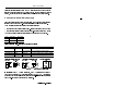
Mold Pressure Module Recommendation for using associated software We recommend the following software to use this module effectively: • To display molding parameters processed by the module, your personal opuer us e euppe n soare ro ! enolo"es# $n% ra&erse y# ’$ • . For instructions on using the software, refer to DARTWin Software Installation and Use manual.
Mold Pressure Module 3 1. What the module does The module processes and extracts cyclic injection molding data for display on your PC, and responds to alarms that you set to monitor critical molding parameters.
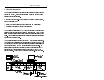
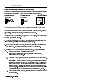
Mold Pressure Module 2. Wire the module ATTENTION: Disconnect all power to the SLC system before wiring.
Mold Pressure Module 5 3. Module I/O Inputs The module has two independent channels that you configure to process signals from machine sensors (default) or from the SLC output image table across the backplane.
Mold Pressure Module Commands and status via the I/O image table The module uses I/O image word 0 for bit-level commands from the SLC processor and returns bit-level status to the SLC processor. You will use these command and status bits in your ladder logic. Addresses: Commands = O:e.0/xx, Status = I:e.
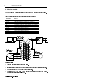
Mold Pressure Module 7 Pressure values transferred from the SLC data table to the module must be integer numbers in units of PSI. If using the Pro-Set 200 Injection Control System, the ladder logic provides pressure values in the correct format. 4. Configure the module with jumper plugs Each channel is independently configurable. Jumper-plug configurations selected here must match G-file bit selections done next in section 5.
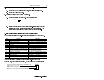
Mold Pressure Module Select the calibration resistor with jumper plugs Select the module’s internal calibration resistor or external resistor located in the sensor or separately wired to the module’s terminal block. Channel 1 Jumper JP3 Cal Res ** Internal 200K default position ** Channel 2 Jumper JP4 Cal Res ** ** ** ** External Jumper Locations Module JP3 JP4 5.
Mold Pressure Module 4. Select the Adv Configuration icon and launch it. Then select/enter: A. B. Length of M0/M1 files at 106 words, each (listed in section 11). A. Change the display radix to hex. You get this display: 9 Length of G file at 94 words. 5. Select and launch the Enter G Data icon. 0 5 10 : 90 B. 404 0 0 : 0 0 0 0 : 0 0 0 0 : 0 0 0 0 : 0 0 0 0 : 0 Select word one (as shown) and enter the bit-selected data word that corresponds to the module’s configuration in your application.
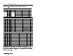
Mold Pressure Module Select the hex-equivalent value from the following table( Bits 07-00 07-05 04 03 02-00 Chnl 1 Data Source Chnl 2 Data Source Hex 0 0 0 0 sensor sensor xx00 0 1 SLC output image tbl sensor xx08 1 0 sensor SLC output image tbl xx10 1 1 SLC output image tbl SLC output image tbl xx18 Bits 11-08 11 10 09 08 Triggers T4 turns alarms OFF? Alarms OFF when T4 Hex 0 0 0 0 ON NO n/a x0xx 0 0 1 0 OFF NO n/a x2xx 0 1 0 0 ON YES Goes ON
Mold Pressure Module 11 6. Set sensor inputs to zero If using a sensor input, zero the channel to cancel any pre-load or offset voltage in the sensor. For mold pressure, zero the channel every machine cycle. The method to zero the channel depends on the type of sensor.
Mold Pressure Module 2. Observe the displayed pressure value. With DARTWin software running on your PC, observe the displayed peak pressure. It should be proportional to the bridge imbalance. 8.
Mold Pressure Module 13 Example 2 Channel 1 Alarm I:8 0000 0 OTHER Channel 2 Alarm I:8 Jump to Alarm Handler JSR Jump To Subroutine SBR File Number U:100 1 OTHER Cycle Time Alarm I:8 2 OTHER Ch. 1 Sensor Loss I:8 3 OTHER Ch. 2 Sensor Loss I:8 4 OTHER 41318 Example 3 Read Channel 1 Sample Data MOV Move Source 0000 Dest I:8.1 0< N7:0 0< Read Channel 1 Sample Data MOV Move Source 0001 Dest I:8.2 0< N7:1 0< 41319 Example 4 Read Frame 1 Status COP Copy File Source #M0:8.
Mold Pressure Module Example 5 Convert counts as read from the module to PSI, where F8:0 = Full load sensor range, in pounds F8:1 = Ejector pin diameter, in inches CPT Compute Dest 0000 Expression F8:2 0.0< ( I:8.1 * F8:0 ) | ( ( F8:1 * F8:1 ) * 2894.58 ) 41321 Example 6 Write Hydraulic Pressure to MPM MOV Move Source N105:1 0< Dest O:8.2 0< 0000 41322 Example 7 Save Channel 1 and 2 Configuration COP Copy File Source #M0:8.0 Dest #N7:0 Length 49 0000 COP Copy File Source #M1:8.
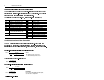
Mold Pressure Module 15 9. Troubleshooting with LEDs LEDs indicate operating conditions detected by the module: INPUT FAULT TRIGGER 1 TxDATA RxDATA Status: Indicates: on loss of a sensor signal, or lo-level sensor is out of range on running a machine cycle flicker transmitting on DartNet flicker receiving on DartNet 10. Use DARTWin software to display processed data Refer to the DARTwin Software Instruction and Use Manual.
Mold Pressure Module 11. Listing of M0/M1 file words You load M0/M1 file data into the module from your PC equipped with DARTwin software. M0 and M1 files contain: • module configuration data, loaded by DARTWin software (words 0-48) • summary data processed by the module (words 49-106) Summary data (in units of A/D counts x 1/100 sec.) is stored in two frames: frame 1 = words 49-75 frame 2 = words 76-106 Important: See summary data notes on page 18.
Mold Pressure Module Frame 1 summary data M0:e.49 M1:e.49 M0:e.50 M1:e.50 M0:e.51 M1:e.51 M0:e.52, 53 M1:e.52, 53 M0:e.54, 55 M1:e.54, 55 M0:e.56, 57 M1:e.56, 57 M0:e.58, 59 M1:e.58, 59 M0:e.60, 61 M1:e.60, 61 M0:e.62, 63 M1:e.62, 63 M0:e.64, 65 M1:e.64, 65 M0:e.66, 67 M1:e.66, 67 M0:e.68 M1:e.68 M0:e.69 M1:e.69 M0:e.70 M1:e.70 M0:e.71 M1:e.71 M0:e.72 M1:e.72 M0:e.73 M1:e.73 M0:e.74 M1:e.74 M0:e.75 M1:e.75 Frame 2 summary data M0:e.76 M1:e.76 M0:e.77 M1:e.77 M0:e.78 M1:e.78 M0:e.79, 80 M1:e.79, 80 M0:e.
Mold Pressure Module Summary data notes Single-word summary values are stored with bytes reversed. You must use the Swap instruction to convert them to integer format. Double-word summary values are stored as integer pairs, with the lowword value stored in the lower address of the pair, high-word value in upper. 12. Specifications Description: Value: electrical backplane current backplane power number of input channels A/D conversion common-mode rejection dynamic response 0.3A @ 5V dc 1.
Mold Pressure Module 19 13. Compliance with European Union Directive If this product has the CE mark it is approved for installation within the European Community or EEA regions. It has been designed and tested to meet the following directives.
Mold Pressure Module 14. CSA Hazardous Location Approval CSA certifies products for general use as well as for use in hazardous locations. CSA certification is indicated by the product label as shown below, and not by statements in any user documentation.
Mold Pressure Module 21 The following warnings apply to products having CSA certification for use in hazardous locations. ! ATTENTION: Explosion hazard: • Substitution of components may impair suitability for Class I, Division 2 • Do not replace components unless power has been switched off or the area is known to be non-hazardous. • Do not disconnect equipment unless power has been switched off or the area is known to be non-hazardous.
Mold Pressure Module Approbation d’utilisation dans des emplacements dangereux par CSA La CSA certifie les produits d'utilisation generale aussi bien que ceux qui s'utilisent dans des emplacements dangereux. La certification CSA en vigueur est indiquee par l'etiquette du produit et non par des affirmations dans la documentation a l'usage des utilisateurs.
Mold Pressure Module 23 Les avertissements suivants s'appliquent aux produits ayant la certification CSA pour leur utilisation dans des emplacements dangereux. ! ATTENTION: Risque d'explosion: • La substitution de composants peut rendre ce materiel inacceptable pour lesemplacements de Classe I, Div. 2. • Couper le courant ou s'assurer quel'emplacement est designe non dangereux avant de remplacer lescomposants.
Mold Pressure Module 24 SLC500™ is a trademark of Rockwell Automation DARTWin™ is a trademark of RJG Technologies Publication 1746-5.13 July 1998 PN 955132-89 Copyright 1998 Rockwell International Corp. Printed in USA.