
User Manual Owner's manual


89 Publication 1746-UM614B-EN-P - September 2007
Appendix
B
Channel Configuration Worksheets
Select your bit configurations. Write them down at the bottom of the worksheet. Use one worksheet for
each channel.
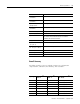
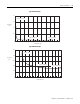
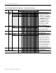
Channel Configuration Word (O:e.0 through O:e.3) — Bit Descriptions
Bit or
Bits
Define To Select Set these bits in the Channel Configuration Word Description
15…1211109876543210
0…3 Input
Typ e
TC Type J
0000
Project ______________
Slot Number __________
Channel Number ______
Configure the channel for the
input type connected to it. Valid
inputs are thermocouples and analog
input signals of ±50 mV and ±100 mV.
You can configure the channel to read
the cold-junction (CJC) temperature.
When reading the CJC temperature,
the channel ignores the physical input
signal.
TC Type K
0001
TC Type T
0010
TC Type E
0011
TC Type R
0100
TC Type S
0101
TC Type B
0110
TC Type N
0111
±50 mV
1000
±100 mV
1001
TC Type C
1010
TC Type D
1011
Invalid 1 1 0 0
Invalid 1 1 0 1
Invalid 1 1 1 0
CJC Temp
1111
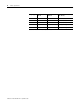
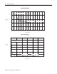
4, 5 Data
Format
Engr. Units x1
00 Select the channel data format
from: Engineering units (EU) x1 or
x10. For EU x1, values are in 0.1
degrees or 0.01 mV. For EU x10,
values are in whole °C or °F or
0.1 mV. Scaled-for-PID (value is
the same for any input type).
Proportional input signal range is
scaled to 0…16,383 counts.
Proportional counts (value is
same for any input type).
Proportional input signal range is
scaled to ±32,767 counts. For more
information, refer to page 49.
Engr. Units x10
01
Scaled-for-PID 10
Counts 11