
User Manual Owner's manual

Publication 1746-UM614B-EN-P - September 2007
72 Application Programming Examples
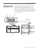
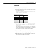
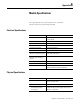
Configuration Word
address 15 data 0 address 15 data 0
N10:0 0000 1001 0001 0000
1112131415 8 674 123
0010000 1 00 01 0000
910
50
15
] [
S:1
MOVE
Source N10:0
Dest O:3.0
MOV
TO BCD
Source I:3.0
Dest
N7:0
TOD
MASKED MOVE
Source N7:0
Mask 0FFF
Dest
O:2.0
MVM
*
END
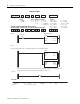
Example Configuration Word with These Parameters:
channel enabled, °F, zero for open-circuit, EU x10, Type J thermocouple
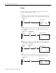
Not Used Channel
Enable
0 = Disable
1 = Enable
Not Used Temp
Units
0 = °C
1 = °F
Response to
Open-circuit
0 0 = zero
0 1 = FS
1 0 = LS
Data
Format
0 0 = EU x1
0 1 = EU x10
1 0 = Scaled PID
1 1 = Prop Counts
Type
of Input
0 0 0 0 = Type J
0 0 0 1 = Type K
0 0 1 0 = Type T
0 0 1 1 = Type E
0 1 0 0 = Type R
0 1 0 1 = Type S
0 1 1 0 = Type B
0 1 1 1 = Type N
1 0 0 0 = 0…100 mV
1 0 0 1 = ±100
1 0 1 0 = Type C
1 0 1 1 = Type D
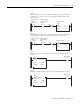
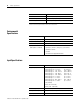
First Pass Bit
Rung 2.0
Rung 2.1
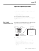
Convert the channel 0 data word (° F) to BCD and write this to the LED indicator display.
Initialize Channel 0
Program
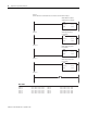
The use of the masked move instruction with the 0FF mask lets you use outputs 12, 13, 14 and 15 for other
output devices in your system. The seven segment display uses outputs 0 …11.
Rung 2.2
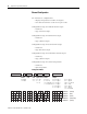
Data Table