
User Manual Owner's manual


65 Publication 1746-UM614B-EN-P - September 2007
Chapter
8
Module Diagnostics and Troubleshooting
This chapter describes troubleshooting with channel-status and
module-status LED indicators. It explains the types of conditions that
might cause the module to flag an error, and suggests what corrective
action you could take. Topics include:
• module and channel diagnostics.
• status indicators.
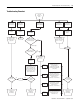
• troubleshooting flowchart.
• replacement parts.
• contacting Rockwell Automation.
Module and Channel
Diagnostics
The module operates at two levels.
• Module level
• Channel level
Module level operation includes functions such as cycling power,
configuration, and communication with the SLC processor. ON
indicates the module is OK. OFF indicates a fault.
Channel level operation includes functions such as data conversion
and open-circuit detection. ON indicates the channel is OK. Blinking
indicates a fault.
The module performs internal diagnostics at both levels, and
immediately indicates detected error conditions with either of its status
LED indicators. When a status LED indicator is continuously ON, the
status is OK.
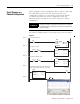
Module Diagnostics When Cycling Power
When you cycle the module’s power, the module performs a series of
internal diagnostic tests. If the module detects a failure, its module
status LED indicator remains off.