
User Manual Owner's manual

Publication 1746-UM614B-EN-P - September 2007
54 Channel Configuration, Data, and Status
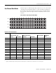
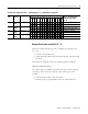
Channel Status Word, Channels 0…3 (I:e.4 through I:e:.7) — Bit Definitions
Bit or
Bits
Reflect/
Indicate
Configured for With This Bit Code Reflects Configuration in
Bits 0…11 and Indicates
Detected Faults in Bits
12…15
1514131211109876543210
0 … 3 Input
Typ e
TC Type J
0000
Reflects the type of channel
input.
TC Type K
0001
TC Type T
0010
TC Type E
0011
TC Type R
0100
TC Type S
0101
TC Type B
0110
TC Type N
0111
±50 mV
1000
±100 mV
1001
TC Type C
1010
TC Type D
1011
Invalid 1 1 0 0 The module faults when it
detects an invalid
configuration.
Invalid 1 1 0 1
Invalid 1 1 1 0
CJC Temp
1111
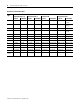
4, 5 Data
Format
Engr. Units x1
00 Reflects the type of data
format.
Engr. Units x10
01
Scaled-for-PID 10
Counts 11
6, 7 Open
Input
Mode
Zero 00 Reflects module response to a
detected open input circuit (for
all input types including CJC
thermistor). The module faults
when it detects an invalid
configuration.
Upscale
01
Downscale 10
Invalid 1 1
8Units
°F, °C
Degrees C 0 Reflects temperature units.
Degrees F
1
9, 10 Unused Unused 00 Faults when it detects a
non-zero value.
11 Chnl
Enable
Channel Off
0 Reflects enabled/disabled
channel status. Status word of
a disabled channel is zero.
Channel data and status words
remain cleared until the
module sets this bit in
response to a new
configuration word.
Channel On
1