
User Manual Owner's manual


45 Publication 1746-UM614B-EN-P - September 2007
Chapter
6
Channel Configuration, Data, and Status
This chapter examines channel configuration and status words, and
explains how you use them. It gives you information about how to:
• configure a channel.
• check a channel’s status.
Channel Configuration
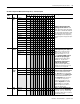
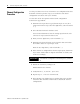
Channel configuration words appear in the SLC controller’s output
image table as shown below. Words 0…3 correspond to module
channels 0…3. Words 4…7 are not used.
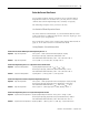
After module installation, you must configure each channel to
establish the way the channel operates (for example, thermocouple
type and temperature units). You configure the channel by setting bits
in the configuration word using your programmer. We present bit
descriptions next.
For information on addressing, using your software and programming,
refer to Chapters 4, 5, and 7, respectively.
SLC Output Image (Configuration) Words
CH
0 Configuration W
ord
0134567891011121314
15
012
2
2
2
34567891011121314
15
0134567891011121314
15
0134567891011121314
15
CH 1 Configuration W
ord
CH 2 Configuration W
ord
CH 3 Configuration W
ord
•
•
O:e.0
O:e.1
O:e.2
O:e.3
O:e.4
O:e.7
Not Used
e = slot number of the module