
User Manual Owner's manual

Publication 1746-UM614B-EN-P - September 2007
36 Preliminary Operating Considerations
Module Addressing
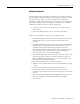
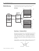
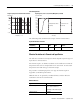
The following memory map shows you how the SLC processor’s
output and input image tables are defined for the module.
Memory Map
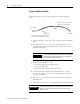
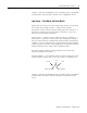
Output Image — Configuration Words
Eight words of the SLC processor’s output image table are reserved for
the module. Output image words 0…3 are used to configure the
module’s input channels 0…3. Each output image word configures a
single channel, and is referred to as a configuration word. Word 5 is
used for calibration. Each word has a unique address based on the
slot number assigned to the module. (The remaining three words are
not used.)
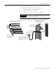
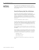
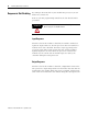
Example Address — If you want to configure channel 2 on the module
located in slot 4 in the SLC chassis, your address would be O:4.2.
Channel 0 Configuration W
ord
Channel 1 Configuration W
ord
Channel 2 Configuration W
ord
Channel 3 Configuration W
ord
Channel 0 Data W
ord
Channel 1 Data W
ord
Channel 2 Data W
ord
Channel 3 Data W
ord
Channel 0 Status W
ord @
Channel 1 Status W
ord @
Channel 2 Status W
ord @
Channel 3 Status W
ord @
W
ords 4, 6, & 7
(not defined)
Slot e
Slot e
W
ord 0
W
ord 1
W
ord 2
W
ord 3
W
ord 7
W
ord 0
W
ord 1
W
ord 2
W
ord 3
W
ord 4
W
ord 5
W
ord 6
W
ord 7
Calibration W
ord W
ord 5
•
•
Bit 15 Bit 0 Ad
Bit 15 Bit 0
Ad
@ returns calibration status during calibration
(Class 1)
Output Image
8 Words
Input Image
8 Words
Output Scan
Input Scan
Output Image
Input Image
Thermocouple
Module Image
Table
Output Image
Input Image
SLC 5/0X
Data Files
O : 4 . 2
File Type
Word DelimiterElement Delimiter
Word
Slot