
User Manual Owner's manual


25 Publication 1746-UM614B-EN-P - September 2007
Chapter
3
Install and Wire the Module
This chapter tells you how to:
• avoid electrostatic damage.
• determine the module’s chassis power requirement.
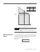
• install the module.
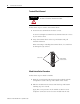
• wire signal cables to the module’s terminal block.
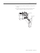
• install the ferrite collar.
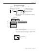
Electrostatic Damage
Electrostatic discharge can damage semiconductor devices inside this
module if you touch backplane connector pins. Guard against
electrostatic damage by observing the following precautions.
• Touch a grounded object to rid yourself of charge before
handling the module.
• Wear an approved wrist strap when handling the module.
• Handle the module from the front, away from the backplane
connector. Do not touch backplane connector pins.
• Keep the module in its static-shield bag when not in use.
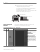
Power Requirements
The module receives its power through the SLC 500 chassis backplane
from the fixed or modular +5V dc/+24V dc chassis power supply. The
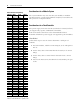
maximum current drawn by the module is shown in this table.
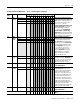
When using the module in a modular system, add the values shown
above to the requirements of all other modules in the SLC chassis to
prevent overloading the chassis power supply.
When using the module in a fixed controller, be sure not to exceed the
power supply rating for the pair of modules in the two slot I/O chassis.
ATTENTION
Electrostatic discharge can degrade performance or cause
permanent damage. Handle the module as stated below.
Maximum Current
5V dc 24V dc
0.11 A 0.085 A