
User Manual Owner's manual


Publication 1746-UM614B-EN-P - September 2007
22 Quick Start
10. Monitor the status of input channel 0 to determine its
configuration setting and operational status.
This is useful for troubleshooting when the blinking channel
LED indicates that an error has been flagged.
If the Module Status LED indicator is off, or if the Channel 0 LED
indicator is off or blinking, refer to Chapter 8.
Channel Configuration
Worksheet
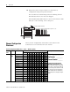
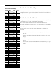
Select your bit configurations. Write them at the bottom of the
worksheet. Use one worksheet for each channel.
Channel 1 Data W
ord
Channel 2 Data W
ord
Channel 3 Data W
ord
Bit
15
Bit 0
W
ord 1
W
ord 2
W
ord 3
Address
I:1.4
Channel 0 Data Word
W
ord 0
W
ord 7
Channel 1 Status W
ord
Channel 2 Status W
ord
Channel 3 Status W
ord
Channel 0 Status Word
0
0
0
0
1
0
0
0
0
0
0
0
0
0
0
0
Input
Type
Data Format
Open Circuit
Type
T
emperature Units
Zero (not used)
Channel Status
Open Circuit Error
Under Range Error
Over Range Error
Configuration Error
•
•
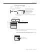
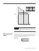
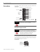
SLC 500 Controller Data Files
Output Image
Input Image
(8 words)
In this example, during normal operation only bit 11 is set.
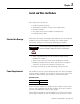
Channel Configuration Word (O:e.0 … O:e.3) — Bit Descriptions
Bit or
Bits
Define To select Set these bits in the Channel Configuration Word Description
15…1211109876543210
0…3 Input
Typ e
TC Type J
0000
Project ______________
Slot Number _________
Channel Number ______
Configure the channel for the
input type connected to it. Valid
inputs are thermocouples and analog
input signals of ±50 mV and ±100 mV.
You can configure the channel to read
the cold-junction (CJC) temperature.
When reading the CJC temperature,
the channel ignores the physical input
signal.
TC Type K
0001
TC Type T
0010
TC Type E
0011
TC Type R
0100
TC Type S
0101
TC Type B
0110
TC Type N
0111
±50 mV
1000
±100 mV
1001
TC Type C
1010
TC Type D
1011
Invalid 1 1 0 0
Invalid 1 1 0 1
Invalid 1 1 1 0
CJC Temp
1111