
User Manual Owner's manual


Publication 1746-UM614B-EN-P - September 2007
20 Quick Start
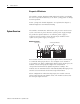
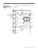
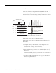
6. Set up Channel 0.
Determine the operating parameters for channel 0. This example
shows the channel 0 configuration word defined with all
defaults (0) except for the channel enable (bit 11=1). Module
assumed in slot 1. (For details on channel configuration, refer to
the configuration worksheet on page 22).
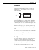
7. Program the transfer of the configuration word.
Program the transfer of the configuration word (from step 6) to
the module.
a. Using the memory map function, create integer file N10.
Integer file N10 should contain one element for each channel
used. (For this example, we used N10:0.).
b. Enter configuration parameters for channel 0 (from step 6)
into N10:0.
In this example, all of the bits of N10:0 are zero except for the
channel enable bit (N10:0/11).
c. Program a ladder logic instruction to copy the contents of
N10:0 to output word O:1.0.
O:1.1
Channel 1 Configuration W
ord
Channel 2 Configuration W
ord
Channel 3 Configuration W
ord
W
ords 4, 6, & 7
(reserved)
Bit
15
Bit 0
W
ord 1
W
ord 2
W
ord 3
Address
O:1.0
0
0
0
0
0
0
0
0
0
0
0
0
0
0
0
0
Channel 0 Configuration Word
W
ord 0
W
ord 7
Input
Type
Data Format
Open Circuit
T
emperature Units
Channel Enable
Unused
0
0
0
0
1
0
0
0
0
0
0
0
0
0
0
0
Use Default Settings For:
Example Settings for Channel 0.
• Type J Thermocouple
• Engineering Units x 1
• Data Word = 0 If Open
Circuit
• Degrees Celsius
O:1.2
O:1.3
O:1.7
Unused
Calibration W
ord 5
•
•
•
•
•
•
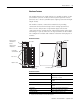
SLC 500 Controller
Data Files
Input Image
Output Image
(8 words)
Set this bit (11) to enable channel. Address = O.1.0/11.