Thermocouple/mV Isolated Input Module Catalog Number 1746-INT4 User Manual
Important User Information Solid state equipment has operational characteristics differing from those of electromechanical equipment. Safety Guidelines for the Application, Installation and Maintenance of Solid State Controls (publication SGI-1.1 available from your local Rockwell Automation sales office or online at http://literature.rockwellautomation.com) describes some important differences between solid state equipment and hard-wired electromechanical devices.
Table of Contents Preface Use This Manual . . . . . . . . . . . . . . . . . . . Who Should Use This Manual . . . . . . . . . Purpose of This Manual. . . . . . . . . . . . . . Additional Resources. . . . . . . . . . . . . . . . Common Techniques Used in this Manual . . . . . . . . . . . . . . . . . . . . . . . . . . . . . . . . . . . . . . . . . . . . . . . . . . . . . . . . . . . . . . . . . . . . . . . . . . . 7 7 7 8 8 Compliance with European Union Directives . . . .
Table of Contents Chapter 7 Ladder Programming Examples Processor Basics . . . . . . . . . . . . . . . . . . . . . . . . . . . . . . Load Channel Configurations for Transfer to the Module Change a Channel Configuration . . . . . . . . . . . . . . . . . . Verify Changes to a Channel Configuration . . . . . . . . . . Process a Channel Input with the PID Instruction . . . . . . Monitor Channel Status Bits . . . . . . . . . . . . . . . . . . . . . . . . . . . . . . . . . . . . . . . .
Table of Contents 5 Appendix D Channel Calibration About the Procedure . . . . . . . . . . . . . . . . . . . . . . . . . . . . .
Table of Contents Publication 1746-UM614B-EN-P - September 2007
Preface Use This Manual Read this preface to familiarize yourself with the rest of the manual. This preface covers the following topics: • • • • • Who Should Use This Manual Who should use this manual The purpose of this manual Terms and abbreviations Conventions used in this manual Allen-Bradley support Use this manual if you are responsible for designing, installing, programming, or troubleshooting control systems that use Allen-Bradley small logic controllers.
Preface Additional Resources The following documents contain information that may be helpful to you as you use Allen-Bradley SLC products. To obtain a copy of any of the Allen-Bradley documents listed, contact your local Allen-Bradley office or distributor.
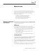
Chapter 1 Module Overview This chapter describes the thermocouple/millivolt isolated input module and explains how the SLC controller reads thermocouple or millivolt analog input data from the module.
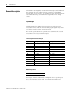
Module Overview General Description The module stores digitally-converted thermocouple and/or millivolt (mV) analog data in its image table for retrieval by all fixed and modular SLC 500 processors. The module supports connections from any combination of up to four thermocouple and/or mV analog sensors. Input Ranges The following tables define thermocouple types and associated temperature ranges and the millivolt analog-input signal ranges that each of the module’s input channel supports.
Module Overview 11 Hardware Features The module fits into any single slot for I/O modules in either an SLC 500 modular system or an SLC 500 fixed system expansion chassis (1746-A2). It is a Class 1(1) module (uses eight input words and eight output words). The module contains a removable terminal block providing connections for four thermocouple and/or analog input devices.
Module Overview Diagnostic LED Indicator The module contains diagnostic LED indicator that help you identify the source of problems that may occur when cycling power or during normal operation. Power cycling and channel diagnostics are explained in Chapter 8, Module Diagnostics and Troubleshooting. System Overview The module communicates with the SLC 500 processor and receives +5V dc and +24V dc power from the system power supply through the parallel backplane interface.
Module Overview 13 System Operation When you cycle power, the module checks its internal circuits, memory, and basic functions. During this time, the module status indicator remains off. If the module finds no faults, it turns on its module status indicator.
Module Overview Module Addressing The module requires eight words each in the SLC processor’s input and output image tables. Addresses for the module in slot e are as follows: I:e.0…3 thermocouple/mV data for channels 0…3, respectively I:e.4…7 status data for channels 0…3, respectively O:e.0…3 configuration data for channels 0…3, respectively O:e.4…7 reserved for future use. Do not use.
Module Overview Block Diagram of Isolated-Channel Input Circuits 15 This illustration shows a block diagram for the analog input circuitry.
Module Overview Publication 1746-UM614B-EN-P - September 2007
Chapter 2 Quick Start Use this chapter as an abbreviated procedure for getting the module into operation or as an overview if you need the additional steps described in subsequent chapters. This chapter assumes that you understand the following things: • SLC 500 products • Electronic process control • Ladder logic instructions Because this chapter is a start-up guide, it does not contain detailed explanations. It does, however, refer to other chapters or to other SLC publications for more information.
Quick Start Procedures IMPORTANT Follow these precautions to prevent damaging the module from electrostatic discharge: • Before handling the module, rid yourself of electric charge by touching a grounded object. • Avoid touching connector terminations and circuit components. • Keep the module in its electrostatic shielded bag when not in use. 1. Unpack the module.
Quick Start 19 3. Install the module. Make sure system power is off; then insert the module into the I/O chassis. In this example procedure, the module is inserted into slot 1. Top and Bottom Module Releases Card Guide 4. Connect thermocouple wires to channel 0 on the module’s terminal block. Make sure both cold-junction compensation (CJC) devices are securely attached. Terminal Block CJC A Device CHL 0+ CHL 0CHL 1+ Important: Ground the thermocouple’s cable shield to the I/O chassis with 9.
Quick Start 6. Set up Channel 0. O:1.0 O:1.1 O:1.2 O:1.3 • • • Word 0 Word 1 Channel 0 Configuration Word Channel 1 Configuration Word Word 2 Channel 2 Configuration Word Word 3 Channel 3 Configuration Word • • • Calibration Word 5 O:1.7 Word 7 Words 4, 6, & 7 (reserved) Input Type Data Format Open Circuit Address Unused Output Image (8 words) Unused Input Image Channel Enable SLC 500 Controller Data Files Temperature Units Determine the operating parameters for channel 0.
Quick Start 21 Data Table Display of Integer File N10:0 address N10:0 15 data 0 0000 1000 0000 0000 Ladder Logic to Transfer N10:0 to the Module: First Pass Bit COP S:1 COPY FILE ] [ 15 Source Dest Length address # N10:0 # O:1.0 1 15 data 0 When cycling power, the first pass bit (S:1/15) is set for one scan, enabling the COPY instruction to transfer the configuration word to the processor’s output image table. From there it is transferred to the module in the processor’s I/O scan. 8.
Quick Start 10. Monitor the status of input channel 0 to determine its configuration setting and operational status. This is useful for troubleshooting when the blinking channel LED indicates that an error has been flagged. If the Module Status LED indicator is off, or if the Channel 0 LED indicator is off or blinking, refer to Chapter 8.
Quick Start 23 Channel Configuration Word (O:e.0 … O:e.3) — Bit Descriptions (Continued) Bit or Bits Define To select 4, 5 Data Format Engr. Units x1 Engr.
Quick Start Publication 1746-UM614B-EN-P - September 2007
Chapter 3 Install and Wire the Module This chapter tells you how to: • • • • • Electrostatic Damage avoid electrostatic damage. determine the module’s chassis power requirement. install the module. wire signal cables to the module’s terminal block. install the ferrite collar. Electrostatic discharge can damage semiconductor devices inside this module if you touch backplane connector pins. Guard against electrostatic damage by observing the following precautions.
Install and Wire the Module Considerations for a Modular System Fixed Controller Compatibility Module INT4 IA4 IA8 IA16 IM4 IM8 IM16 OA8 OA16 IB8 IB16 IV8 IV16 IG16 OV8 OV16 OB8 OG16 OW4 OW8 OW16 IO4 I08 IO12 NI4 NIO4I NIO4V DCM HS OB16 IN16 INT4 BAS OB32 OV32 IV32 IB32 OX8 NO4I NO4V ITB16 ITV16 KE KEn OBP16 NT4 FIO4I FIO4V Yes Yes Yes Yes Yes Yes Yes Yes Yes Yes Yes Yes Yes Yes Yes Yes Yes Yes Yes Yes Yes Yes Yes Yes Yes Yes Yes Yes Yes Yes Yes Yes Yes Yes Yes Yes 5V dc A 0.035 0.050 0.085 0.
Install and Wire the Module 450 (455, 0) 400 (85) Module 5V dc 24V dc OA8 INT4 0.185 0.110 0 0.085 Total 0.295 0.085 27 350 300 (295, 85) (295) x 5V dc Current 250 (mA) (255, 180) 200 150 100 50 (0, 180) 50 100 150 200 24V dc Current (mA) IMPORTANT Module Installation and Removal Some analog I/O modules, such as the 1746-FIO4I, 1746-FIO4V, 1746-NO4I, and 1746-NO4V, may require an additional 24V dc power supply. For those modules, as needed, refer to the user manual.
Install and Wire the Module Terminal Block Removal ATTENTION Never install, remove, or wire modules with power applied to the chassis or devices wired to the module. Follow these steps to remove the terminal block. 1. Loosen the two terminal-block release screws. To avoid cracking the terminal block, alternate between screws as you remove them. 2. Grasp the terminal block at the top and bottom and pull outward and down.
Install and Wire the Module 29 3. Cover unused slots with the Card Slot Filler, catalog number 1746-N2. 4. To remove, press the releases at the top and bottom of the module, and slide the module out of the chassis slot.
Install and Wire the Module Wire the Module The module contains a green, 18-position, removable terminal block. Terminal Block (Terminal Block Spare Part Catalog Number 1746-RT32) CJC Assembly Release Screw CJC A+ Channel 0+ CJC A- Channel 0Channel 1+ Do NOT use these connections See page 26. Channel 1Channel 2+ Channel 2Channel 3+ CJC B- Channel 3- CJC Assembly CJC B+ n/c Release Screw ATTENTION Do not connect to this terminal.
Install and Wire the Module 31 Wiring Considerations Thermocouple inputs are highly susceptible to electrical noise due to the small signal amplitudes (microvolt/°C). Most applications require that the processor and I/O chassis be installed in an industrial enclosure to reduce the effects of electrical interference. Consider the following conditions when selecting a slot location for the module.
Install and Wire the Module Prepare and Wire the Cables Follow these steps to prepare and connect cable leads and drain wires. (Remove foil shield and drain wire from sensor-end of the cable.) Signal Wires Cable Drain Wire Signal Wires (At the module-end of the cable, extract the drain wire but remove the foil shield.) 1. At each end of the cable, strip some casing to expose individual wires. 2. Trim signal wires to 12.5 cm (5 in.) lengths beyond the cable casing and strip about 4.76 mm (3/16 in.
Install and Wire the Module 33 7. At the source-end of cables from mV devices: – remove the drain wire and foil shield. – apply shrink wrap as an option. – connect to mV devices keeping the leads short. IMPORTANT If noise persists, try grounding the opposite end of the cable, instead. (Ground one end only.) Cable Preparation and Connections to Minimize Electrical Noise Interference Ungrounded End at Source Device Grounded End at I/O Chassis 9.5 mm (3/8 in.) Wires 9.5 mm (3/8 in.
Install and Wire the Module Install the Ferrite Collar For immunity to electrical noise with this CE-marked module, insert a ferrite collar (Fair-Rite Inc. part number 0443164151) around the input cables immediately beneath the module in the I/O chassis. Follow these steps to install the ferrite collar. 1. Bundle the cables at the module end. 2. Fold the collar so that it encircles the cables. 3. Press the plastic housing until the collar snaps together. 4. Check that the collar is fully latched. 5.
Chapter 4 Preliminary Operating Considerations This chapter explains how the module and the SLC processor communicate through the processor’s I/O image tables. It also describes the module’s input filter characteristics. Topics discussed include: • • • • Module ID Code module ID code. module addressing. input channel characteristics. response to slot disabling. The module ID code is a unique number assigned to each type of 1746 I/O module.
Preliminary Operating Considerations Module Addressing The following memory map shows you how the SLC processor’s output and input image tables are defined for the module.
Preliminary Operating Considerations 37 Chapter 6, Channel Configuration, Data, and Status, gives you detailed bit information about the data content of the configuration word. Input Image — Data Words and Status Words Eight words of the SLC processor’s input image table are reserved for the module. Input image words 0…3 (data words) hold the temperature values of thermocouple analog inputs for channels 0…3.
Preliminary Operating Considerations Input Channel Characteristics Each channel has an 8 Hz digital filter for input noise rejection, a multiplexer for processing cold junction compensation (CJC) values, and an analog-to-digital (A/D) converter to provide digital values for SLC processing.
Preliminary Operating Considerations 39 Cut-off Frequencies Frequency Response of the 8 Hz Filter Converter Step Response (worst case) for Filter, Multiplexer, and A/D Attenuation % of Final Value 00 db 100% 90% 80% 70% 60% 50% 40% 30% 20% 10% 6 -25db -50db 6 6 -75db Multiplex CJC Values (200 ms) A/D Conversion (200 ms) -100db 1 5 10 50 100 0 60 120 180 240 Frequency — Hz 300 360 420 480 540 600 Time (ms) The following table summarizes the input channel characteristics: Inpu
Preliminary Operating Considerations Response to Slot Disabling By writing to the status file in your modular SLC processor you can disable any chassis slot. Refer to your SLC programming manual for the slot disable/enable procedure. ATTENTION Always understand the implications of disabling the module before using the slot disable feature. Input Response When the slot for this module is disabled, the module continues to update its inputs.
Chapter 5 Access Files to Configure I/O There are two ways to configure the SLC chassis for a 1746-INT4 module. You can either click and drag items from the list or you can use the Read IO Config method. Click and Drag Configuration Follow these steps to configure the SLC chassis by clicking and dragging modules. 1. Double-click the menu item to open the IO Configuration menu in the RSLogix 500 software. 2. Place the 1746-INT4 module into the correct slot by clicking and dragging from the list.
Access Files to Configure I/O The I/O Configuration is now complete. Each slot shows the corresponding module that is located on the rack. In this example, 1746-INT4 is in slot 1. Read IO Config Method Follow these steps to configure the SLC chassis by using the read I/O configuration method. 1. Double-click the menu item to open the IO Configuration menu in the RSLogix 500 software.
Access Files to Configure I/O 43 2. Place the 1746-INT4 module into the correct slot by clicking Read IO Config. The following screen appears. 3. Select either the driver and processor node number or click Who Active to browse for the device. • If you selected the driver and node number, proceed to step 5. • If you clicked Who Active, the following screen appears.
Access Files to Configure I/O The Who Active screen lets you to browse for the SLC device. 4. Locate the SLC chassis under the appropriate driver and click OK. You return to the Read IO Config dialog. 5. Click Read IO Config and the rack is populated automatically. The I/O Configuration is now complete. Each slot shows the corresponding module that is located on the rack. In this example, the 1746-INT4 is in slot 1.
Chapter 6 Channel Configuration, Data, and Status This chapter examines channel configuration and status words, and explains how you use them. It gives you information about how to: • configure a channel. • check a channel’s status. Channel Configuration Channel configuration words appear in the SLC controller’s output image table as shown below. Words 0…3 correspond to module channels 0…3. Words 4…7 are not used.
Channel Configuration, Data, and Status The configuration word default settings are all zero.
Channel Configuration, Data, and Status 47 Channel Configuration Word (O:e.0 through O:e.3) — Bit Descriptions Bit or Bits Define 0…3 Input Type To Select TC Type J TC Type K TC Type T TC Type E TC Type R TC Type S TC Type B TC Type N ±50 mV ±100 mV TC Type C TC Type D Invalid Invalid Invalid CJC Temp Engr. Units x1 Engr.
Channel Configuration, Data, and Status Channel Configuration Word (O:e.0 through O:e.3) — Bit Descriptions (Continued) Bit or Bits Define To Select 9, 10 Unused Unused 11 Chnl Enable Channel Off Channel On 12…15 Unused Unused Enter Your Bit Selections >> Set these bits in the Channel Configuration Word Description 15…12 11 10 9 8 7 6 5 4 3 2 1 0 0 0 These bits must be zero for a valid configuration. 0 Disable unused channels for faster response.
Channel Configuration, Data, and Status 49 Select the Correct Data Format To provide the highest display resolution, select Scaled-for-PID or Proportional Counts. To use either one, you may have to convert channel data to/from Engineering Units, manually or logically. The following examples show you how to do this.
Channel Configuration, Data, and Status Channel Configuration Procedure Use this procedure once for each channel to set configuration bits that determine channel operation. Copy it as needed to write down configuration selections of all your channels. Use the table of bit descriptions and the blank configuration worksheet in Appendix B. 1. Determine the input device type (thermocouple or mV) for a channel and enter its respective four digit binary code in bit field 0…3. 2.
Channel Configuration, Data, and Status Use Channel Data Words 51 Thermocouple or millivolt input data reside in I:e.0 to I:e.3 of the SLC controller’s input image file (where e is the slot number assigned to the module). The values depend on the input type and data format that you select. When an input channel is disabled, its data word is reset (0). SLC Controller’s Input Image File (Data Word) O:e.0 CH 0 Channel Data Word 15 14 13 12 11 10 O:e.
Channel Configuration, Data, and Status Resolution of a Channel Data Word Input Type Data Format Engineering Units x 10 Engineering Units x 1 Scaled-for-PID ° Celsius ° Fahrenheit ° Celsius ° Fahrenheit ° Celsius C 1 °C/step 1 °F/step 0.1 °C/step 0.1 °F/step D 1 °C/step 1 °F/step 0.1 °C/step J 1 °C/step 1 °F/step K 1 °C/step T Proportional Counts ° Fahrenheit ° Celsius ° Fahrenheit 0.1414 °C/step 0.2564 °C/step 0.0353 °C/step 0.0641 °C/step 0.1 °F/step 0.1414 °C/step 0.
Channel Configuration, Data, and Status Use Channel Status Words 53 Channel status words are stored in the SLC controller’s input image file at addresses I:e.4 to I:e.7 (where e is the slot number assigned to the module). Status words 4…7 correspond to and reflect the configuration of channels 0…3 (O:e.0…O:e.3). Whenever a channel is disabled (O:e.x/11 = 0), its corresponding status word is zero. This condition tells you that input data contained in the channel data word is invalid and should be ignored.
Channel Configuration, Data, and Status Channel Status Word, Channels 0…3 (I:e.4 through I:e:.7) — Bit Definitions Bit or Bits Reflect/ Indicate 0…3 Input Type Configured for With This Bit Code Reflects Configuration in 15 14 13 12 11 10 9 8 7 6 5 4 3 2 1 0 Bits 0…11 and Indicates Detected Faults in Bits 12…15 0 0 0 0 TC Type J TC Type K 0 0 0 1 TC Type T 0 0 1 0 TC Type E 0 0 1 1 TC Type R 0 1 0 0 TC Type S 0 1 0 1 Reflects the type of channel TC Type B 0 1 1 0 input.
Channel Configuration, Data, and Status 55 Channel Status Word, Channels 0…3 (I:e.4 through I:e:.7) — Bit Definitions (Continued) Bit or Bits Reflect/ Indicate 12 Open Input 13 Underrange 14 Overrange 15 Invalid Config Configured for With This Bit Code Reflects Configuration in 15 14 13 12 11 10 9 8 7 6 5 4 3 2 1 0 Bits 0…11 and Indicates Detected Faults in Bits 12…15 Diagnostics 0 Condition not detected. 1 Detected open input. Diagnostics 0 Condition not detected. 1 Detected under-range input.
Channel Configuration, Data, and Status Out-of-range Detection (Bit 13 for under-range, bit 14 for over-range) The module tests all enabled channels for an out-of-range condition each time it scans its inputs. Possible causes of an out-of-range condition include: • the temperature is too hot or too cold for the thermocouple being used. • a type B, C, or D thermocouple may be registering a °F value in EU x1 beyond the range allowed by the SLC processor (beyond 32,767) for the data word.
Chapter 7 Ladder Programming Examples Earlier chapters explained how configuration words define channel operation. This chapter shows examples of ladder logic that you write to: • load configurations into the output image file to be scanned to the module. • change the configuration of a channel. • verify that the change in configuration occurred. • process a channel input value with a PID instruction. • monitor channel status. We start with some basic concepts of the SLC processor.
Ladder Programming Examples During the I/O scan, the SLC processor scans configuration words from its output image file to the module, and scans data and status words from the module to its input image file. The SLC processor scans its I/O following each program scan. We repeat the configuration word because it is used often in the examples.
Ladder Programming Examples 59 2. Program a rung of ladder logic to copy the integer file #N10 into output image file O:3.0 through O:3.3. First Pass Bit S:1 ] [ 15 Initialize NT4 COP COPY FILE Source #N10:0 Dest #O:3.0 Length 4 When cycling power, bit S:1/15 is set for the first program scan.
Ladder Programming Examples Program Rung 2:0 Set up all four channels COP COPY FILE Source #N10:0 Dest #O:3.0 4 Length S:1 ] [ 15 Rung 2:1 Set channel 2 to CJC I:1.0 ] [ 0 Rung 2:2 MOV B3 [OSR] 0 MOVE Source N10:4 Dest O:3.2 Set channel 2 back to Type K I:1.0 ]/[ 0 MOV B3 [OSR] 1 MOVE Source N10:2 Dest O:3.2 Rung 2:3 END IMPORTANT While the module changes the channel configuration, it does not monitor inputs to any channel.
Ladder Programming Examples Verify Changes to a Channel Configuration 61 When changing a channel configuration, there is always a delay until the ladder logic reads the new data word based on the new configuration. Therefore, it is important to verify that the module successfully stored the new channel configuration word. The following example explains how to verify a change to a channel configuration.
Ladder Programming Examples Process a Channel Input with the PID Instruction The module was designed to input a channel directly to a PID instruction of an SLC 5/02 processor or later without the need of an intermediate scale operation. EXAMPLE Use channel data as the process variable for the PID instruction. Use channel data as the process variable for the PID instruction. 1. Select scaled-for-PID as the data type in the channel configuration word. 2.
Ladder Programming Examples Monitor Channel Status Bits 63 This example shows how you could monitor the open-circuit error bit of each channel and set an alarm bit if the module detects an open input. An open-circuit error can occur if a thermocouple or CJC thermistor wire breaks or becomes disconnected from the terminal block. In this example, we monitor the channel enable bit (bit 11) and the open-input bit (bit 12) in channel status words I:3.4 through I:3.7, and use output image bits O:2.
Ladder Programming Examples Program Rung 2:0 First Pass Bit S:1 ] [ 15 Rung 2:1 Channel 0 Status I:3.4 ] [ 11 Channel 0 Open I:3.4 ] [ 12 Channel 0 Alarm O:2.0 ( ) 0 Rung 2:2 Channel 1 Status I:3.5 ] [ 11 Channel 1 Open I:3.5 ] [ 12 Channel 1 Alarm O:2.0 ( ) 1 Rung 2:3 Channel 2 Status I:3.6 ] [ 11 Channel 2 Open I:3.6 ] [ 12 Channel 2 Alarm O:2.0 ( ) 2 Rung 2:4 Channel 3 Status I:3.7 ] [ 11 Channel 3 Open I:3.7 ] [ 12 Channel 3 Alarm O:2.
Chapter 8 Module Diagnostics and Troubleshooting This chapter describes troubleshooting with channel-status and module-status LED indicators. It explains the types of conditions that might cause the module to flag an error, and suggests what corrective action you could take. Topics include: • • • • • Module and Channel Diagnostics module and channel diagnostics. status indicators. troubleshooting flowchart. replacement parts. contacting Rockwell Automation. The module operates at two levels.
Module Diagnostics and Troubleshooting Channel Diagnostics When a channel is enabled, the module checks for a valid configuration. Then on each scan of its inputs, the module checks for out-of-range and open-circuit fault conditions of its inputs including the CJC thermistor. When the module detects a failure of any channel diagnostic test, it causes the channel status LED indicator to blink and sets the corresponding channel fault bit (bits 12…15 of the channel status word).
Module Diagnostics and Troubleshooting 67 Module-status and Channel-status LED Indicators If Module Status LED Indicator is And Channel Status LED Indicator is Then Take This Corrective Action On On The channel is enabled. No action required. Blinking The module detected: open-circuit condition under-range condition over-range condition channel configuration error.
Module Diagnostics and Troubleshooting Out-of-range Detection (Bit 13 for under-range, bit 14 for over-range) The module tests all enabled channels for an out-of-range condition each time it scans its inputs. Possible causes of an out-of-range condition include the following: • The temperature is too hot or too cold for the thermocouple being used. • A type B thermocouple may be registering a °F value in EU x1 beyond the range allowed by the SLC processor (beyond 32,767) for the data word.
Module Diagnostics and Troubleshooting 69 Troubleshooting Flowchart Check LED indicators on module. Module Status LED indicator off. Module Status LED indicator on. Module fault condition. Normal module operation. Check to see that module is seated properly in chassis. Cycle power. Channel Status LED indicator(s) blinking. Channel Status LED indicator off. Channel Status LED indicator on. Channel is not enabled. Channel enabled and working properly. Fault condition.
Module Diagnostics and Troubleshooting Replacement Parts Contacting Rockwell Automation The module has the following replaceable parts.
Chapter 9 Application Programming Examples This chapter provides two application examples to help you use the module. • Basic example • Supplementary example The basic example lets you display a temperature. The supplementary example lets you manually select the display of temperature in °C or °F. Basic Example (to display a temperature) This example lets you display the temperature of a bath °F on an LED indicator display device.
Application Programming Examples Configuration Word 5 4 3 2 1 0 Type Data of Input Format 0 0 0 0 = Type J 0 0 = EU x1 0 0 0 1 = Type K 0 1 = EU x10 0 0 1 0 = Type T 1 0 = Scaled PID 1 1 = Prop Counts 0 0 1 1 = Type E 0 1 0 0 = Type R Example Configuration Word with These Parameters: 0 1 0 1 = Type S channel enabled, °F, zero for open-circuit, EU x10, Type J thermocouple 10 9 15 14 13 12 11 Not Used Channel Not Used Enable 0 = Disable 1 = Enable 0 0 0 0 1 0 0 8 Temp Units 0 = °C 1 = °F 1 7 6
Application Programming Examples Supplementary Example (select display in °C or °F) 1746-INT4 73 This example shows how to display the temperature of several thermocouples at display panel. A selector switch (I:2/0) lets the operator choose between displaying temperatures in °C or °F. A second selector switch (I:2/1) lets the operator switch a display between the ambient temperature near the bath and the temperature inside the control cabinet containing the SLC controller.
Application Programming Examples Channel Configuration All channels are configured for: • display temperature to tenths of a degree. • zero data word in the event of an open-circuit. Configuration setup for ambient thermocouple: • channel 0. • type T thermocouple. Configuration setup for bath thermocouple: • channel 1. • type J thermocouple. Configuration setup for steam thermocouple: • channel 2. • type K thermocouple. Configuration setup for chilled H2O thermocouple: • channel 3.
Application Programming Examples 75 Program Setup Follow these steps to set up the program. 1. Set up two configuration words for each channel in file N10, one for °C and the other for °F. Include two configuration words for the CJC temperature in the cabinet containing the SLC controller. N10 Channels/Configuration Words Channel Configuration Word Addresses °F °C 0 N10:0 N10:4 1 N10:1 N10:5 2 N10:2 N10:6 3 N10:3 N10:7 CJC N10:8 N10:9 2.
Application Programming Examples Program The first six rungs change channel configurations based on the position of the two selector switches. Rung 2.0 If the degrees selector switch is switched to Fahrenheit, configure all four channels to read in degrees Fahrenheit. The default for channel 0 is to read the ambient temperature thermocouple. Degrees Selector Switch = Configure Channels Fahrenheit COP B3 I:2.0 COPY FILE ] [ OSR Source #N10:0 0 0 Dest Length #O:1.0 4 Rung 2.
Application Programming Examples 77 Rung 2.4 If the ambient/cabinet selector switch is switched to ambient, and the degrees selector switch is switched to Celsius, configure channel 0 to read the ambient temperature thermocouple in degrees Celsius. Degrees Selector Switch = Fahrenheit I:2.0 ]/[ 0 Ambient/Cabinet Selector Switch = Ambient B3 I:2.0 ] [ OSR 4 1 Configure Channels MOV MOVE Source N10:4 Dest O:1.0 Rung 2.
Application Programming Examples Rung 2.8 Convert data words to BCD format and send them to the LED indicator displays. Write Ambient or Cabinet Temperature to the Display TOD Rung 2.9 TO BCD Source I:1.0 Dest O:3.0 Write Bath Temperature to the Display TOD Rung 2.10 TO BCD Source I:1.1 Dest O:4.0 Write Steam Temperature to the Display TOD Rung 2.11 TO BCD Source I:1.2 Dest O:5.0 Write Chilled Temperature to the Display TOD TO BCD Source I:1.3 Dest O:6.0 Rung 2.
Appendix A Module Specifications This appendix lists the specifications for the 1746-INT4 Thermocouple/mV Isolated Input Module. Electrical Specifications Attribute Value Backplane current consumption 110 mA @ 5V dc 85 mA @ 24V dc Backplane power consumption 0.6 W max (0.
Module Specifications Attribute Value Max wire size Two 1.6 mm (14 AWG) wires per terminal Max cable impedance 150 Ω max loop impedance, for < 1LSB error Terminal strip Removable, catalog number 1746-RT32 (1) Refer to the thermocouple manufacturer for the correct extension wire.
Module Specifications 81 Attribute Value Temperature scale (selectable) °C or °F and 0.1 °C or 0.1 °F Millivolt scale, dc (selectable) 0.1 mV or 0.01 mV Open-circuit detection leakage current 20 nA typical Open-circuit detection (selectable) Upscale, downscale, or zero Time to detect open-circuit 5 s, typical Input step response 0…99.9% in 600 ms (worst case) Input resolution See Input Resolution Graphs on following pages.
Module Specifications Input Type Max Error (1) @ 25 °C Max Error (1) @ 77 °F Temperature Drift (1) (0… 60 °C) N ±1.79 °C ±3.23 °F ±0.080 °C/°C, °F/°F C ±2.28 °C ±4.11 °F ±0.270 °C/°C, °F/°F D ±2.52 °C ±4.54 °F ±0.280 °C/°C, °F/°F ±50 mV ±50 µV ±50 µV ±0.5 µV/°C ±50 ppm/°C ±100 mV ±50 µV ±50 µV ±0.5 µV/°C ±50 ppm/°C (1) Assumes the module terminal block temperature is stable.
Module Specifications 83 Thermocouple Resolution Type C Thermocouple 0.4 0.32 oC @ 2000 oC 0.3 0.26 oC @ 0 oC Resolution (˚C) 0.20 oC @ 1000 oC 0.2 0.1 0 0 250 500 750 1000 1250 1500 1750 2000 2250 Temperature (˚C) Type D Thermocouple 0.4 0.34 oC @ 0 oC 0.27 oC @ 2000 oC 0.3 Resolution (˚C) 0.20 oC @ 1100 oC 0.2 0.
Module Specifications Type J Thermocouple .25 .20 0.18 oC @ -200 oC .15 Resolution (˚C) .10 0.06 oC @ 275 oC 0.05 oC @ 750 oC .05 0 -300 -150 0 150 300 450 600 750 900 Temperature (˚C) Type K Thermocouple 4.0 3.4 oC @ -250 oC 3.0 Resolution (˚C) 2.0 1.0 0.08 oC @ 550 oC 0 -300 -150 0 150 300 450 600 750 Temperature (˚C) Publication 1746-UM614B-EN-P - September 2007 0.
Module Specifications 85 Type E Thermocouple 2.0 1.70 oC @ -250 oC 1.5 Resolution (˚C) 1.0 0.5 0.05 oC @ 1000 oC 0.04 oC @ 365 oC 0 -300 -150 0 150 300 450 600 750 900 1050 1200 Temperature (˚C) Type R Thermocouple 0.75 0.68 oC @ 0 oC 0.60 Resolution (˚C) 0.45 0.26 oC @ 885 oC 0.28 oC @ 1750 oC 0.30 0.
Module Specifications Type S Thermocouple 0.75 0.68 oC @ 0 oC 0.60 Resolution (˚C) 0.45 0.31 oC @ 1750 oC 0.31 oC @ 885 oC 0.30 0.15 0 -300 -150 0 150 300 450 600 750 900 1050 1200 1350 1500 1650 1800 Temperature (˚C) Type T Thermocouple 2.0 1.7 oC @ -250 oC 1.5 Resolution (˚C) 1.0 0.5 0.08 oC @ 65 oC 0 -300 -150 0 150 Temperature (˚C) Publication 1746-UM614B-EN-P - September 2007 0.
Module Specifications 87 Type B Thermocouple 1.20 1.13 oC @ 300 oC 0.90 Resolution (˚C) 0.60 0.38 oC @ 1060 oC 0.31 oC @ 1800 oC 0.30 0 -300 -150 0 150 300 450 600 750 900 1050 1200 1350 1500 1650 1800 1950 Temperature (˚C) Type N Thermocouple 0.170 0.150 0.13 oC @ 0 oC 0.125 Resolution (˚C) 0.09 oC @ 500 oC 0.09 oC @ 1100 oC 0.100 0.075 0.050 0.
Module Specifications Publication 1746-UM614B-EN-P - September 2007
Appendix B Channel Configuration Worksheets Select your bit configurations. Write them down at the bottom of the worksheet. Use one worksheet for each channel. Channel Configuration Word (O:e.0 through O:e.3) — Bit Descriptions Bit or Bits Define To Select 0…3 Input Type TC Type J TC Type K TC Type T TC Type E TC Type R TC Type S TC Type B TC Type N ±50 mV ±100 mV TC Type C TC Type D Invalid Invalid Invalid CJC Temp Engr. Units x1 Engr.
Channel Configuration Worksheets Channel Configuration Word (O:e.0 through O:e.
Channel Configuration Worksheets 91 Select your bit configurations. Write them down at the bottom of the worksheet. Use one worksheet for each channel. Channel Configuration Word (O:e.0 through O:e.3) — Bit Descriptions Bit or Bits Define 0…3 Input Type 4, 5 Data Format 6, 7 Opencircuit Mode To Select TC Type J TC Type K TC Type T TC Type E TC Type R TC Type S TC Type B TC Type N ±50 mV ±100 mV TC Type C TC Type D Invalid Invalid Invalid CJC Temp Engr. Units x1 Engr.
Channel Configuration Worksheets Channel Configuration Word (O:e.0 through O:e.3) — Bit Descriptions (Continued) Bit or Bits Define To Select 8 Units °F, °C Degrees C Degrees F 9, 10 Unused Unused 11 Chnl Enable Channel Off Channel On 12…15 Unused Unused Enter Your Bit Selections >> Set these bits in the Channel Configuration Word Description 15…12 11 10 9 8 7 6 5 4 3 2 1 0 0 Select °C/°F for thermal inputs. Ignored for mV inputs. Important: For 1 EU x1 and °F (0.
Channel Configuration Worksheets 93 Select your bit configurations. Write them down at the bottom of the worksheet. Use one worksheet for each channel. Channel Configuration Word (O:e.0 through O:e.3) — Bit Descriptions Bit or Bits Define 0…3 Input Type 4, 5 Data Format 6, 7 Opencircuit Mode To Select TC Type J TC Type K TC Type T TC Type E TC Type R TC Type S TC Type B TC Type N ±50 mV ±100 mV TC Type C TC Type D Invalid Invalid Invalid CJC Temp Engr. Units x1 Engr.
Channel Configuration Worksheets Channel Configuration Word (O:e.0 through O:e.3) — Bit Descriptions (Continued) Bit or Bits Define To Select 8 Units °F, °C Degrees C Degrees F 9, 10 Unused Unused 11 Chnl Enable Channel Off Channel On 12…15 Unused Unused Enter Your Bit Selections >> Set these bits in the Channel Configuration Word Description 15…12 11 10 9 8 7 6 5 4 3 2 1 0 0 Select °C/°F for thermal inputs. Ignored for mV inputs. Important: For 1 EU x1 and °F (0.
Channel Configuration Worksheets 95 Select your bit configurations. Write them down at the bottom of the worksheet. Use one worksheet for each channel. Channel Configuration Word (O:e.0 through O:e.3) — Bit Descriptions Bit or Bits Define 0…3 Input Type 4, 5 Data Format 6, 7 Opencircuit Mode To Select TC Type J TC Type K TC Type T TC Type E TC Type R TC Type S TC Type B TC Type N ±50 mV ±100 mV TC Type C TC Type D Invalid Invalid Invalid CJC Temp Engr. Units x1 Engr.
Channel Configuration Worksheets Channel Configuration Word (O:e.0 through O:e.3) — Bit Descriptions (Continued) Bit or Bits Define To Select 8 Units °F, °C Degrees C Degrees F 9, 10 Unused Unused 11 Chnl Enable Channel Off Channel On 12…15 Unused Unused Enter Your Bit Selections >> Set these bits in the Channel Configuration Word Description 15…12 11 10 9 8 7 6 5 4 3 2 1 0 0 Select °C/°F for thermal inputs. Ignored for mV inputs. Important: For 1 EU x1 and °F (0.
Appendix C Thermocouple Descriptions The descriptions of thermocouples J, K, T, E, R, and S were extracted from NBS Monograph 125 (IPTS–68) issued March 1974. We also describe types C and D. J Type Thermocouple (iron versus copper-nickel ) The J thermocouple is the least suitable for accurate thermometry because there are significant nonlinear deviations in the thermoelectric output from different manufacturers.
Thermocouple Descriptions ASTM Standard E230-72 in the Annual Book of ASTM Standards [1972] specifies that the standard limits of error for Type J commercial thermocouples be ±2.2 °C (±35.9 °F) between 0…277 °C (32…531 °F) and ±3/4% between 277…760 °C (531…1400 °F). Limits of error are not specified for Type J thermocouples below 0 °C (32 °F) or above 760 °C (1400 °F). Type J thermocouples can also be supplied to meet special limits of error, which are equal to one half the limits given above.
Thermocouple Descriptions 99 ASTM Standard E230-72 in the Annual Book of ASTM Standards [1972] specifies that the standard limits of error for Type K commercial thermocouples be ±2.2 °C (±35.9 °F) between 0…277 °C (32…530.6 °F) and ±3/4% between 277…1260 °C (530.6…2300 °F)/ Limits of error are not specified for the Type K thermocouples below 0 °C (32 °F). Type K thermocouples can also be supplied to meet special limits of error, which are equal to one half the standard limits of error given above.
Thermocouple Descriptions Type T thermoelements are not well suited for use in nuclear environments, since both thermoelements are subject to significant changes in composition under thermal neutron irradiation. The copper in the thermoelement is converted to nickel and zinc. Because of the high thermal conductivity of Type TP thermoelements, special care should be exercised in the use of the thermocouples to insure that both the measuring and reference junctions assume the desired temperatures.
Thermocouple Descriptions 101 ASTM Standard E230-72 in the Annual Book of ASTM Standards [1972] specifies that the standard limits of error for the Type E commercial thermocouples be ±1.7 °C (±35 °F) between 0…316 °C (32…600 °F) and ±1/2% between 316…871 °C (600…1600 °F). Limits of error are not specified for Type E thermocouples below 0 °C (32 °F). Type E thermocouples can also be supplied to meet special limits of error, which are less than the standard limits of error given above ±1.25 °C (±34.
Thermocouple Descriptions C and D Type Thermocouples C (tungsten-5% rhenium versus tungsten-26% rhenium) D (tungsten-3% rhenium versus tungsten-25% rhenium) Publication 1746-UM614B-EN-P - September 2007 Types C and D thermocouples are recommended for use in the temperature range from 0…2320 °C (32…4208 °F) in non-oxidizing inert atmospheres. They are not practical for use below 399 °C (750 °F). Beware of embrittlement. C and D Thermocouple Recommended Use Code Color Code Max Useful Temp.
Appendix D Channel Calibration This appendix shows you how to calibrate the module’s input channels. About the Procedure The purpose of the procedure is to store a pair of calibration values in EEPROM for each channel to set channel accuracy at 0.05% of full range regardless of channel circuit tolerances. The module is designed so you can calibrate its input channels individually or in groups. The thermocouple/mV operation of all channels is suspended during calibration.
Channel Calibration Calibration Codes and Status Use the following format for entering calibration code words and reading calibration status bits. You enter calibration values in Hex. You can read channel status OK bits at different steps in the calibration procedure, one bit for each channel you are calibrating.
Channel Calibration 105 Calibration Procedure To perform this calibration procedure, you need a precision dc voltmeter and precision power supply that displays and maintains a calibration voltage to 1/1000 of a millivolt: at 0.000 mV and 90.000 mV. Prepare for calibration by removing the thermocouple leads from the input terminals of the channels that you want to calibrate. Switch the SLC processor to Run mode so it can execute the calibration ladder logic.
Channel Calibration 8. Observe bits 4…7 in status word 4. If all the channels you are calibrating see 90.000 mV, the module returns status-OK bits set, one bit for each channel (F Hex for all four channels). Otherwise, the module returns channel status bits set to zero. 9. Remove the 90.000 mV calibration voltage. 10. With your programming terminal, enter calibration code 1008 Hex into the data table address for configuration word 5. 11. Observe bits 0…3 in status word 5.
Appendix E CSA Hazardous Location Approval CSA Hazardous Location Approval Approbation d’utilisation dans des emplacements dangereux par la CSA CSA certifies products for general use as well as for use in hazardous locations. Actual CSA certification is indicated by the product label as shown below, and not by statements in any user documentation. La CSA certifie les produits d’utilisation générale aussi bien que ceux qui s’utilisent dans des emplacements dangereux.
CSA Hazardous Location Approval CSA Hazardous Location Approval Approbation d’utilisation dans des emplacements dangereux par la CSA The following warnings apply to products having CSA certification for use in hazardous locations. Les avertissements suivants s’appliquent aux produits ayant la certification CSA pour leur utilisation dans des emplacements dangereux. ATTENTION Explosion hazard — •Substitution of components may impair suitability for Class I, Division 2.
Glossary Terms and Abbreviations The following terms and abbreviations are used throughout this manual. For definitions of terms not listed here refer to the Industrial Automation Glossary, Allen-Bradley publication AG-7.1. A/D Refers to the analog-to-digital converter within the module. The converter produces a digital value whose magnitude is proportional to the instantaneous magnitude of an analog input signal. attenuation The reduction in the magnitude of a signal as it passes through a system.
Glossary configuration word Contains the channel configuration information needed by the module to configure and operate each channel. The module is designed for software rather than hardware configuration. cut-off frequency The frequency at which the input signal is attenuated 3 dB by the digital input filter. Frequency components of the input signal below the cut-off frequency are passed with under 3 dB of attenuation. dB (decibel) A logarithmic measure of the ratio of two signal levels.
Glossary 111 input data scaling Depends on the data format that you select for the channel data word. You can select from scaled-for-PID or Engineering Units for millivolt, thermocouple, or CJC inputs, which are automatically scaled. You may also select proportional counts, which you must compute to fit your application’s temperature or voltage resolution. local system A control system with I/O chassis within several feet of the processor, and using 1746-C7 or 1746-C9 ribbon cable for communication.
Glossary status word Contains status information about the channel’s current configuration and operational state. You can use this information in your ladder program to determine whether the channel data word is valid. step response time This is the time required for the module to process an input signal to reach 99.9% of its expected final value, given a large step change in the input signal.
Index A accessing files for IO cofiguration 41 B block diagram 15 C cables preparing and wiring 32 channel config worksheet 22 configuration 45 configuration procedure 50 cut off frequency 38 data 45 data words 51 status 45 status words 53 cold junction compensation 30 compatibility with cables 14 millivolt devices 14 thermocouples 14 D data words 37 diagnostic LEDs 12 E electrostatic damage 25 EMC directive 9 European Union directives 9 EMC directive 9 low voltage directive 9 F ferrite collar 34 G ge
Index S selecting correct data format 49 slot disabling 40 input response 40 output response 40 status words 37 step response 38 system overview 12 compatibility with cables 14 compatibility with millivolt devices 14 compatibility with thermocouple 14 module addressing 14 module operation 13 operation 13 Publication 1746-UM614B-EN-P - September 2007 T terminal block removal 28 U update time 38 using channel data words 51 using channel status words 53 W wiring 30 cold junction compensation 30 consi
Rockwell Automation Support Rockwell Automation provides technical information on the Web to assist you in using its products. At http://support.rockwellautomation.com, you can find technical manuals, a knowledge base of FAQs, technical and application notes, sample code and links to software service packs, and a MySupport feature that you can customize to make the best use of these tools.