
Quick Start User Manual


16 Thermocouple/mV Isolated Input Module
Publication 1746-QS002B-EN-P - July 2002
Troubleshoot the Module
Monitor the status of input channel 0 to determine its configuration setting and
operational status. This is useful for troubleshooting when the flashing channel LED
indicates that an error has been flagged. If the module status LED is off, or if the
channel 0 LED is off or flashing, refer to step 8.
TIP
For more detailed information on these procedures, refer to
Chapter 8 (Module Diagnostics and Troubleshooting) of the
user manual.
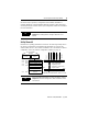
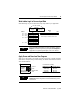
Channel 1 Data W
ord
Channel 2 Data W
ord
Channel 3 Data W
ord
Output Image
SLC 500 Controller
Data Files
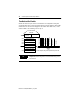
Bit
15
Bit 0
W
ord 1
W
ord 2
W
ord 3
Address
I:1.4
Input Image
Channel 0 Data W
ordW
ord 0
W
ord 7
(8 words)
Channel 1 Status W
ord
Channel 2 Status W
ord
Channel 3 Status W
ord
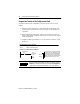
Channel 0 Status W
ord
0
0
0
0
1
0
0
0
0
0
0
0
0
0
0
0
Input
Type
Data Format
Open Circuit
Type
T
emperature Units
Zero (not used)
Channel Status
Open Circuit Error
Under Range Error
Over Range Error
Configuration Error
For this example, during normal operation only bit 11 is set.