
Quick Start User Manual


Thermocouple/mV Isolated Input Module 15
Publication 1746-QS002B-EN-P - July 2002
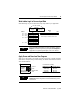
Write Ladder Logic to Process Input Data
Write ladder logic to process the thermocouple input data for your application:
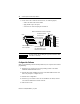
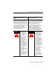
Apply Power and Download Your Program
Apply power. Download your program to the SLC and put the controller into RUN
mode. In this example, during a normal startup, the module status LED and channel
status 0 LED illuminate.
TIP
For more detailed information on these procedures, refer to
Chapter 7 (Ladder Programming Examples) and Chapter 9
(Application Programming Examples) of the user manual.
TIP
For more detailed information on these procedures, refer to
Chapter 8 (Module Diagnostics and Troubleshooting) of the
user manual.
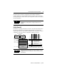
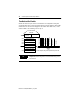
Channel 1 Data W
ord
Channel 2 Data W
ord
Channel 3 Data W
ord
Output Image
SLC 500 Controller
Data Files
Bit
15
Bit 0
W
ord 1
W
ord 2
W
ord 3
Address
I:1.0
Input Image
0
0
0
0
0
0
0
0
0
0
0
0
0
0
0
0
Channel 0 Data W
ord
W
ord 0
W
ord 7
(8 words)
Channel 1 Status W
ord
Channel 2 Status W
ord
Channel 3 Status W
ord
Channel 0 Status W
ord
(V
ariable
Thermocouple Input Data)
Address
I:1.0
I:1.1
I:1.2
I:1.3
I:1.7
In this example, the module is located in slot 1.
0
1
2
3
INPUT
Channel
LEDs
Module Status
LED
MODULE STATUS
THERMOCOUPLE/mV
CHANNEL
STATUS
ISOLATED
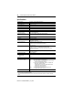
If channel LED is blinking:
Module detected: and status word:
open circuit
under range
over range
config error
bit 12 = 1
bit 13 = 1
bit 14 = 1
bit 15 = 1