
Quick Start User Manual

Thermocouple/mV Isolated Input Module 13
Publication 1746-QS002B-EN-P - July 2002
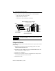
No manual entry of special I/O configuration (SPIO CONFIG) information is
required. Module ID code automatically assigns the number of input and output
words required by the module. Refer to your configuration software documentation
for more information..
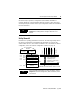
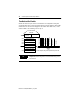
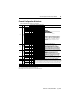
Set Up Channel 0
Determine the operating parameters for channel 0. The following example shows
the channel 0 configuration word defined with all defaults (0) except for the
channel enable (bit 11-1). The module is installed in slot 1. For details on channel
configuration, refer to the channel configuration worksheet on page 19.
TIP
For more detailed information on these procedures, refer to
Chapter 5 (Accessing Files to Configure I/O)of the user
manual.
TIP
For more detailed information on these procedures, refer to
Chapter 6 (Channel Configuration, Data and Status) of the
user manual.
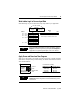
O:1.1
Channel 1 Configuration W
ord
Channel 2 Configuration W
ord
Channel 3 Configuration W
ord
W
ords 4, 6, & 7
(reserved)
Output Image
SLC 500 Controller
Data Files
Bit
15
Bit 0
W
ord 1
W
ord 2
W
ord 3
Address
O:1.0
Input Image
0
0
0
0
0
0
0
0
0
0
0
0
0
0
0
0
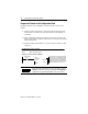
Channel 0 Configuration Word
W
ord 0
W
ord 7
Input
Type
Data Format
Open Circuit
T
emperature Units
Channel Enable
Unused
(8 words)
0
0
0
0
1
0
0
0
0
0
0
0
0
0
0
0
Use Default Settings For:
Example Settings for Channel 0.
Set this bit (11) to enable channel. Address = O:1.0/11.
Type
J Thermocouple
Engineering
Units x 1
Data
W
ord = 0 If Open Circuit
Degrees
Celsius
O:1.2
O:1.3
O:1.7
Unused
Calibration W
ord 5