Quick Start Thermocouple/mV Isolated Input Module Cat. No. 1746-INT4 Contents Use this document as a guide to install and wire the 1746-INT4 module. If you need more detailed information, refer to the Thermocouple/mV Isolated Input Module User Manual, publication 1746-6.16.
Thermocouple/mV Isolated Input Module Important User Information Because of the variety of uses for the products described in this publication, those responsible for the application and use of these products must satisfy themselves that all necessary steps have been taken to assure that each application and use meets all performance and safety requirements, including any applicable laws, regulations, codes and standards.
Thermocouple/mV Isolated Input Module ATTENTION ! 3 Environment and Enclosure This equipment is intended for use in a Pollution Degree 2 industrial environment, in overvoltage Category II applications (as defined in IEC publication 60664-1), at altitudes up to 2000 meters without derating. This equipment is considered Group 1, Class A industrial equipment according to IEC/CISPR Publication 11.
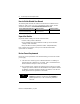
Thermocouple/mV Isolated Input Module How to Get the Related User Manual The following table describes the related user manual that is available for this module. To order a copy or to view or download an online version, visit The Automation Bookstore at: www.theautomationbookstore.com For more detailed information about: See this document: Publication number: Installation, configuration, programming, diagnostics and troubleshooting Thermocouple.mV Isolated Input Module User Manual 1746-6.
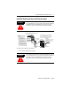
Thermocouple/mV Isolated Input Module 5 Install the Module and Connect the Thermocouples WARNING ! If you insert or remove the module while backplane power is on, an electrical arc can occur. This could cause an explosion in hazardous location installations. Be sure that power is removed or the area is nonhazardous before proceeding. Insert/remove the module into/from the I/O chassis (slot 1 in this example procedure). Important: Thermocouple inputs are highly susceptible to electrical noise.
Thermocouple/mV Isolated Input Module 2. Align the circuit board of the thermocouple module with the card guides located at the top and bottom of the chassis. 3. Slide the module into the chassis until both top and bottom retaining clips are secured. Apply firm even pressure on the module to attach it to its backplane connector. Never force the module into the slot. 4. Cover unused slots with the card slot filler, catalog number 1746–N2. 5.
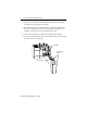
Thermocouple/mV Isolated Input Module 7 Remove/Install the Removable Terminal Block The module ships with an attached an 18-position removable terminal block (RTB). When you install the module, it is not necessary to remove the RTB. If you ever need to remove it, follow this procedure: 1. Alternately loosen the two retaining screws to avoid cracking the RTB. CJC sensors retaining screws RTB 2. Grasp the RTB at the top and bottom and pull outward and down.
Thermocouple/mV Isolated Input Module 2. Make certain the color of the RTB mathces the color band on the module. ATTENTION Inserting a wired RTB on an incorrect module can damage the module’s circuitry when power is restored. ! 3. View the write–on label to identify the slot, chassis and module type. SLOT RACK MODULE 4. Align the RTB retaining screws with the mating connector on the module. Be careful not to damage the CJC sensors. CJC sensors retaining screws RTB 5.
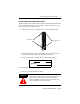
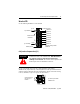
Thermocouple/mV Isolated Input Module 9 Wire the RTB Use the following illustration to wire the RTB: Retaining Screw CJC A+ CJC Assembly Channel 0+ CJC A- Channel 0Channel 1+ Channel 1- Do NOT use these connections Channel 2+ Channel 2Channel 3+ CJC B+ CJC Assembly CJC BRetaining Screw n/c Channel 3spare part catalog number: 1746-RT32 Cold Junction Compensation (CJC) ATTENTION ! Do not remove or loosen the cold junction compensating thermistors located on the terminal block.
Thermocouple/mV Isolated Input Module Wiring Guidelines Follow these guidelines when planning your system wiring. • To limit the pickup of electrical noise, keep thermocouple and millivolt signal wires away from power and load lines. • For high immunity to electrical noise, use Alpha 5121 (shielded, twisted pair) or equivalent wire for millivolt sensors; or use shielded, twisted pair thermocouple extension lead wire specified by the thermocouple manufacturer.
Thermocouple/mV Isolated Input Module 11 Preparing and Wiring the Cables To prepare and connect cable leads and drain wires, follow these steps: Remove the foil shield and drain wire from sensor-end of the cable Signal Wires Extract the drain wire but remove the foil shield, at the module-end of the cable. Drain Wire Signal Wires 1. At each end of the cable, strip some casing to expose individual wires. 2. Trim signal wires to 5–inch lengths beyond the cable casing. Strip about 3/16 inch (4.
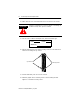
Thermocouple/mV Isolated Input Module 7. At • • • the source-end of cables from mV devices (see following figure): remove the drain wire and foil shield apply shrink wrap as an option connect to mV devices keeping the leads short Make unshielded wires as short as possible. Solder drain wires to braid at casing. Wires 3/8 Signal Wires Connect I/O chassis bolt to earth ground 3/8 Chnl 0 Chnl 1 Chnl 2 Cables Make unshielded wires as short as possible.
Thermocouple/mV Isolated Input Module 13 No manual entry of special I/O configuration (SPIO CONFIG) information is required. Module ID code automatically assigns the number of input and output words required by the module. Refer to your configuration software documentation for more information.. For more detailed information on these procedures, refer to Chapter 5 (Accessing Files to Configure I/O)of the user manual. TIP Set Up Channel 0 O:1.0 O:1.1 O:1.2 O:1.
Thermocouple/mV Isolated Input Module Program the Transfer of the Configuration Word Program the transfer of the configuration word (from previous section) to the module: 1. Using the memory map function, create integer file N10. Integer file N10 should contain one element for each channel used. For this example, we used N10:0. 2. Enter configuration parameters for channel 0 (from previous section) into N10:0. In this example, all the bits of N10:0 are zero except for the channel enable bit (N10:0/11).
Thermocouple/mV Isolated Input Module 15 Write Ladder Logic to Process Input Data Write ladder logic to process the thermocouple input data for your application: SLC 500 Controller Data Files Input Image (8 words) Output Image Address I:1.0 I:1.1 I:1.2 I:1.3 I:1.
Thermocouple/mV Isolated Input Module Troubleshoot the Module Monitor the status of input channel 0 to determine its configuration setting and operational status. This is useful for troubleshooting when the flashing channel LED indicates that an error has been flagged. If the module status LED is off, or if the channel 0 LED is off or flashing, refer to step 8.
Thermocouple/mV Isolated Input Module 17 The following information applies when operating this equipment in hazardous locations: Informations sur l’utilisation de cet équipement en environnements dangereux : Products marked “CL I, DIV 2, GP A, B, C, D” are suitable for use in Class I Division 2 Groups A, B, C, D, Hazardous Locations and nonhazardous locations only. Each product is supplied with markings on the rating nameplate indicating the hazardous location temperature code.
Thermocouple/mV Isolated Input Module Specifications Module Location SLC chassis - any I/O module slot except 0 Input from System Backplane 5Vdc @ 0.110 A, 24Vdc @ 0.
Thermocouple/mV Isolated Input Module 19 Channel Configuration Worksheet Channel Configuration Word (O:e.0 through O:e.3) - Bit Descriptions Bit(s) 0-3 4, 5 Define To Select Input Type TC Type J TC Type K TC Type T TC Type E TC Type R TC Type S TC Type B TC Type N 50mV 100mV TC Type C TC Type D Invalid Invalid Invalid CJC Temp. Data Format Set these bits in the Channel Configuration Word 15-12 11 10 9 8 7 6 Open Circuit Mode 0 0 Engr.
Publication 1746-QS002B-EN-P - July 2002 Supersedes Publication 1746-10.2 - October 1997 PN 957689-85 Copyright © 2002 Rockwell Automation, Inc. All rights reserved. Printed in the U.S.A.