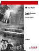
Stepper Controller Module (Catalog No.
Important User Information Because of the variety of uses for the products described in this publication, those responsible for the application and use of this control equipment must satisfy themselves that all necessary steps have been taken to assure that each application and use meets all performance and safety requirements, including any applicable laws, regulations, codes and standards.
European Communities (EC) Directive Compliance If this product has the CE mark it is approved for installation within the European Union and EEA regions. It has been designed and tested to meet the following directives.
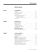
Table of Contents Table of Contents Preface Using This Manual Overview . . . . . . . . . . . . . . . . . Contents of this Manual. . . . . . . Intended Audience . . . . . . . . . . Conventions . . . . . . . . . . . . . . . Rockwell Automation Support . . Local Product Support . . . . . Technical Product Assistance On the Web . . . . . . . . . . . . . . . Chapter 1 . . . . . . . . . . . . . . . . . . . . . . . . . . . . . . . . . . . . . . . . . . . . . . . . . . . . . . . . . . . . . . . . . . .
Table of Contents ii Chapter 3 Start Up and Troubleshooting Chapter Objectives . . . System Start Up. . . . . . Normal Operation . . . . Troubleshooting . . . . . Safety Precautions . . . . Removing the Module . Chapter 4 Chapter 5 . . . . . . . . . . . . . . . . . . . . . . . . . . . . . . . . . . . . . . . . . . . . . . . . . . . . . . . . . . . . . . . . . . . . . . . . . . . . . . . . . . . . . . . . . . . . . . . . . . . . . . . . . . . . . . . . . . . . . . . . . . . . . . .
Chapter 6 Table of Contents iii Home to Proximity Limit Switch and Marker . . . . . . . . . Programming Simple Moves . . . . . . . . . . . . . . . . . . . . . . . General Information. . . . . . . . . . . . . . . . . . . . . . . . . . . Data File Structures . . . . . . . . . . . . . . . . . . . . . . . . . . . Using the N Files for Motion Commands. . . . . . . . . . . . Quadrature Encoder Input . . . . . . . . . . . . . . . . . . . . . . Use of Direct Inputs. . . . . . . . . . . . . . . . . . . . . . . .
Table of Contents iv Appendix B Index Publication 999-121 - December 1999 Input/Output Quick Reference
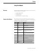
Preface Using This Manual Overview Read this chapter to familiarize yourself with the rest of the manual. It provides information concerning the: • • • • Contents of this Manual 1 contents of this manual intended audience conventions used hazards of injury or equipment damage This manual provides specific information relevant to the Stepper Controller Module, Catalog Number 1746–HSTP1. The following table identifies the chapters, titles and contents.
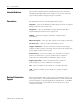
P-2 Using This Manual Intended Audience This manual is designed for the qualified first time user who has a working knowledge of SLC 500™ products. If necessary, obtain the proper training before using the Stepper Controller. Conventions The following terms are used throughout this manual: Input file – refers to the Module's Input Data file. This file is updated during the SLC Processor input scan Output file – refers to the Module's Output Data file.
Using This Manual P-3 Local Product Support Contact your local Rockwell Automation representative for: • • • • sales and order support product technical training warranty support support service agreements Technical Product Assistance If you need to contact Rockwell Automation for technical assistance, please review the information in this manual. If the problem persists, call your local Rockwell Automation representative.
P-4 Using This Manual Publication 999-121 - December 1999
Chapter 1 Module Overview Chapter Objectives The Module overview will permit you to understand the basic functions of the Module and hardware requirements. Stepper Controller The Module, catalog number 1746–HSTP1, is an SLC 500 family compatible device. It can be used with any SLC 500 Processor. The Module is configured through the SLC 500 backplane and requires no switch settings. Motion can be programmed in either direction for over ±8,000,000 counts of absolute position.
1-2 Module Overview Differential inputs are provided for: • Encoder Channel A and A NOT • Encoder Channel B and B NOT • Encoder Marker Channel Figure 1.1 Stepper Module Overview Stepper Controller SLC Power Supply 7 to 24V DC User Power Supply 1 SLC Processor 1 2 Standard I/O Module Stepper Translator Optional Encoder Optional Feedback Wiring Stepper Motor Control Wiring to Translator 2 Power Wires The 24V may be obtained from the SLC Power Supply depending on application power requirements.
Module Overview 1-3 The Module can be configured to: • Determine which inputs are used. • Determine the active level of inputs used. • Set whether just the encoder marker or a prox limit switch and encoder marker combination is used for homing. • Determine if a quadrature encoder will be used. • Select whether the Module output is a pulse train with direction command or a CW pulse train and CCW pulse train. • Select between configuration mode and command mode. NOTE: Some output combinations are not valid.
1-4 Module Overview LED Indicator Diagnostics There are five diagnostic LED indicators provided as shown below. Their purpose is to aid in identifying operational problems. Figure 1.2 LED Indicators Processor and System O.K.
Module Overview Input/Output Terminals 1-5 These terminals supply power and inputs to the Module and outputs to attached devices. Each can accommodate two #14 gauge wires. Figure 1.
1-6 Module Overview Publication 999-121 - December 1999
Chapter 2 Installation and Wiring Chapter Objectives This chapter provides information which permits you to properly unpack, install and wire the interfaces between the Module and the various Stepper Translators that can be used with the Module. Also covered are typical input circuitry (direct input and encoder input), and encoder timing information and encoder feedback connections.
2-2 Installation and Wiring Wiring Refer to the following information on typical interface requirements before beginning this procedure. ATTENTION ! The following information is merely a guide for proper installation. The Allen-Bradley Company cannot assume responsibility for the compliance or the noncompliance to any code, national, local or otherwise for the proper installation of this drive or associated equipment.
Installation and Wiring 2-3 Figure 2.1 Differential Input Typical Input Connection (Refer to page 6-6) User Power Supply 7-24V DC (+) (-) (-) (+) 16 AWG 16 AWG Driver Stepper Controller Voltage Regulator 1 Electrical Cabinet Ground Bus External Internal 2 3 4 5 18 Wiring to Optocoupler Interface The following diagrams show the circuitry used to interface the Module to a Stepper Translator through two different optocoupler devices.
2-4 Installation and Wiring Figure 2.
Installation and Wiring Wiring to Optocoupler Interface (Continued) 2-5 Figure 2.3 Individually Isolated Optocoupler 7-24V DC Typical Input Connection (+) (-) 16 AWG 16 AWG 10 CCW Limit 9 CW Limit Typical Driver Stepper Controller Voltage Regulator 1 Electrical Cabinet Ground Bus 220 W 2 3 +PLS Pulse Input -PLS -20mA Max. 220 W 4 5 +CW/CCW Direction Input -CW/CCW -20mA Max.
2-6 Installation and Wiring Figure 2.4 TTL Interface 5V 7-24V DC Typical Input Connection (Refer to page 6-6) (+) (-) (-) 16 AWG Stepper Controller 5V DC Voltage Regulator 1 (+) Driver External 16 AWG Internal Electrical Cabinet Ground Bus 2 3 4 5 18 Typical Input Circuitry Two basic circuits are used for inputs to the Module. One type is the direct input circuit for home limit switches, overtravel limits, and interrupt devices. The second type is for encoder inputs.
Installation and Wiring 2-7 Figure 2.6 Encoder input equivalent circuit HI 210 LO 210 Typical Encoder Timing Diagram A typical encoder timing diagram is shown below. For actual connections, consult your encoder manufacturer's timing diagram. For all encoder types, if the direction (phasing) of the feedback is backwards, correct this condition by reversing the channel A and channel B connections. STEP 3 Channel A is high at least part of marker interval. Connect to CH A.
2-8 Installation and Wiring Encoder Feedback Connections The following two diagrams illustrate encoder connections to the Module inputs for both 5-volt and 15-volt encoder power supplies. The -notes" included with each diagram provide specifics on wiring. Figure 2.
2-9 Installation and Wiring Figure 2.
2-10 Installation and Wiring Publication 999-121 - December 1999
Chapter 3 Start Up and Troubleshooting Chapter Objectives This chapter contains information that will help you perform the following start up, troubleshooting, and error handling procedures. System Start Up The following instructions apply to initial start up of a Module. 1. Apply power to the SLC system and to the attached input and output devices. 2. Configure the SLC Processor and the Module as instructed in Chapter 4 of this manual. 3.
3-2 Start Up and Troubleshooting More detailed troubleshooting information is provided in the following list: Problem Resolution No green RUN LED Either a major Module malfunction or lack of power from the backplane is indicated. Check for power from the backplane first; if power is present, the Module must be replaced. Red FLT LED is lit Module is improperly configured. Refer to the topic, “Configuration Mode” in Chapter 4 of this manual for additional information.
Start Up and Troubleshooting 3-3 Safety Precautions ATTENTION ! Severe injury or death can result from electrical shock, burn, or unintended actuation of controlled equipment. Hazardous voltages may exist in the control cabinet even with the circuit breaker in the off position. Recommended practice is to disconnect and lock out control equipment from power sources, and discharge stored energy in capacitors, if present.
3-4 Start Up and Troubleshooting Publication 999-121 - December 1999
Chapter 4 Module Operation Chapter Objectives The information in this chapter will give you a basic understanding of frequency outputs and pulse train configuration which must be considered in the application of the Module. Module Overview The Module is an SLC family compatible Module. It is designed for use with an SLC 500™, SLC 5/01™, SLC 5/02™, SLC 5/03™, SLC 5/04™,or SLC 5/05™ Processor. The motion profile execution is independent of the scan time of the SLC Processor once it is initiated.
4-2 Module Operation Command The Command mode directs all stepper motor operations, through the Stepper Translator. There are translators which require a pulse train and direction to operate. Other translators require a CW (positive direction) pulse train and a CCW (negative direction) pulse train. The CW and CCW designations refer to directions of stepper motor rotation. The Stepper Controller can be configured for either type of translator.
Module Operation 4-3 programmed velocity data. Use the Jog+ or Jog– to initiate and stop the motion. IMPORTANT Turning the appropriate bit on will cause the axis to move. Turning it off causes the axis to decelerate and stop. Origin (Home) Search Sequence of Operation Information on this subject is contained in Chapter 4 of this manual, within the topic, “Find Home +/(CW), Find Home –/(CCW)”.
4-4 Module Operation Publication 999-121 - December 1999
Chapter 5 Configuration and Programming Chapter Objectives This chapter provides information to help you configure both the SLC Processor and the Module. This chapter also contains instructions for correctly programming the Module for the command mode of operation. Programming Conventions Since the SLC Processor does not support numbers as large as 8,000,000, the number must be entered as two distinct integer values that can be programmed within the capabilities of the SLC Processor.
5-2 Configuration and Programming Processor configuration using APS 1. Locate an open slot in your chassis. The Module can be used with any SLC Processor. 2. Assign your SLC Processor, if not done previously: a. Using APS, press F3 (Offline PRG/DOC), F1 (PROCSSR FUNCTNS) and F1 (CHANGE PROCSSR) again to assign your processor and Module. b. Press F2 to select a processor or F5 to assign a Module. 3. Assign the Module to an open slot: a. Using APS, highlight an open slot. b. Press F5 (MODIFY SLOT).
Configuration and Programming 5-3 Use the EDT–DAT function to enter parameters into your bit or integer files. IMPORTANT Module Configuration The HHT has a default radix of binary for the bit file (#B) and integer for the integer file (#N). Radices cannot be changed. General Information The Module must be properly configured before any operations may begin. The Module enters the configuration mode on power up, or upon setting the configuration output word 0 mode bit (15) to 1.
5-4 Configuration and Programming upon by the Module until a valid configuration is received. The configuration file has the following format. 15 14 13 12 11 10 9 8 7 6 5 4 3 2 1 0 OUTPUT WORD 0 OUTPUT WORD 1 OUTPUT WORD 2 OUTPUT WORD 3 Output word 0: defines the user's configuration; that is, what types of inputs are present. IMPORTANT Publication 999-121 - December 1999 To guard against a configuration error, certain bits in output word 0 must be set.
Configuration and Programming 5-5 bit 10 1 when output pulse type is pulse train and direction 0 when output pulse type is CW pulse train and CCW pulse train bit 11 not used bit 12 0 for limit switch home operations 1 for marker pulse home operations bit 13 and 14 not used bit 15 1 for configuration mode 0 for command mode Output word 1: Defines the active levels of the inputs.
5-6 Configuration and Programming Configuration mode input image table The data format of the input image table when the Module is in the configuration mode is: Input word 0: bits 0-5, 8-10 identical to like numbered bits in output table bits 6, 7 and 11 not used bit 13 configuration error: 1 = error; 0 = no error bit 14 Module OK: 1 = Module operational, 0 = fatal error encountered bit 15 1 when in configuration mode 0 when in command mode Input word 1: bits 0-5 same as corresponding bits in out
Configuration and Programming 5-7 word 0 bit 13, to be true and turn on the red FLT LED indicator if attempted. • A configuration file that does not provide the ability to home the Module, either by means of a home limit switch and home limit switch operations, or quadrature encoder and marker pulse operations. • A configuration file that does not contain a limit endpoint, either CW or CCW. • A configuration file that specifies both quadrature encoder and diagnostic feedback.
5-8 Configuration and Programming Programming Command Mode Output Words – SLC Processor to Stepper Controller Output Command Word 0 Bit Definition 15 14 13 12 11 10 9 8 7 6 5 4 3 2 1 0 Decimal Value WORD 0 Absolute Move 1 Relative Move 2 Hold Motion 4 Resume Move 8 Immediate Stop (pulse train off) 16 Find Home + CW 32 Find Home - CCW 64 Jog + CW 128 Jog - CCW 256 Preset Position Reset Errors 1024 Program Blend Move Profile 2048 Read Blend Data 4096 Run Blend Move Pro
Configuration and Programming 15 14 13 12 11 10 9 8 7 6 5 4 3 2 1 0 Word 1 reserved WORD 1 15 14 13 12 11 10 9 8 7 6 5 4 3 2 1 0 Word 2 Position MSW 0-to 8388 (1000s) WORD 2 15 14 13 12 11 10 9 8 7 6 5 4 3 2 1 0 Word 3 Position LSW 0-999 (1s) WORD 3 15 14 13 12 11 10 9 8 7 6 5 4 3 2 1 0 Word 4 Velocity (pulses/sec) MSW (1000s) 0-250 WORD 4 15 14 13 12 11 10 9 8 7 6 5 4 3 2 1 0 Word 5 Velocity LSW (1s) 0 to 999 pulses/sec WORD 5 15 14 13 12 11 10 9 8
5-10 Configuration and Programming Output Command Bits for Word 0 Publication 999-121 - December 1999 Bit Description 0 Absolute Move 1 Relative Move 2 Hold Motion 3 Resume Move 4 Immediate Stop (pulse train off) 5 Find Home +/(Up) 6 Find Home –/(Down) 7 Jog +/(Up) 8 Jog –/(Down) 9 Preset Position 10 Reset Errors 11 Program Blend Move Profile 12 Read Blend Data 13 Run Blend Move Profile 14 Preset Encoder Position 15 Mode Flag:1 Configuration Mode 0 Command Mode
Configuration and Programming Notes: 5-11 1. A 0 to 1 transition of the above control bits must occur to cause the associated operation to take place. 2. Reaching either the CW or CCW limit switch during a normal move or jog operation is treated in the same manner as a pulse train enable/disable input. That is, the motor stops and the current position becomes invalid.
5-12 Configuration and Programming In an absolute move, the number of pulses generated by the Module equals the difference between the target position (destination) and the current position. In a relative move, the target position defines the distance (in pulses) that must be traveled relative to the current position.
Configuration and Programming 5-13 Hold move command: causes a controlled deceleration to the starting speed and stop. Upon completion of the hold stop, the hold state input (bit 2, word 0) of the command mode input word image table is set. While the hold move is in effect, velocity and acceleration or deceleration parameters can be changed. Specifying a new position, however, has no effect.
5-14 Configuration and Programming speed and runs at that speed until the home limit switch is contacted or marker is detected (depending on which is configured), and then stops. Without a home proximity limit switch present, the axis speed moves at the configured starting speed until the home limit switch is detected. In this instance, the normal acceleration/deceleration and velocity parameters are disregarded.
Configuration and Programming 5-15 Note: If you are using a home limit switch and a home proximity limit switch and a right to left home command is required to home the axis, mount the home proximity limit switch to the right of the home limit switch. If a left to right home command is required, mount the limit switches opposite to the above. See the diagrams below to properly locate the home limit switches.
5-16 Configuration and Programming Module to output one pulse in the specified direction. This is referred to as a “one shot jog,” and can be made to occur during any 0 to 1 transition of the jog bit, while the velocity is set to zero speed. Preset position: sets the current axis position to the programmed value. The desired position value is copied into the current position input words. If the position is currently invalid, issuing the preset position command causes the position to become valid.
Configuration and Programming 5-17 Using the N Files for Motion Commands The following example is used to denote an axis move equal to 1001 pulse counts, in the CW (+) direction. Word N9:23 contains the information in the (LSW) words which is the fine position in counts. These values can range from 0 to 999. Coarse position information is stored in word N9:22. The combination of coarse and fine position information determines how many counts the axis moves.
5-18 Configuration and Programming terminals 6 through 11, respectively. The Module responds to these direct inputs as follows: • External Interrupt Input – When this input is turned on, the axis decelerates to the programmed starting speed, and then stops. This input works only when a jog operation is being performed. The axis does not stop if this input is activated during any other type of move operation.
Configuration and Programming 5-19 means the axis position must be valid for a blend move operation to take place. The first segment of each blend move profile always starts at the programmed starting speed and accelerates up to the programmed velocity. The starting speed for the next segment in the profile is equal to the velocity specified for the previous segment.
5-20 Configuration and Programming 5. Resetting the send next blend move data bit causes the SLC Processor to reset the read blend data bit (O:2/12). 6. The Module again sets the send next blend move data bit in response to resetting the read blend data bit. 7. The sequence described in steps 3 – 6 is repeated until all the segments making up the blend move profile have been read. The minimum number of segments is 2; the maximum number is 16. 8.
Configuration and Programming 5-21 Publication 999-121 - December 1999
5-22 Configuration and Programming Module Status Inputs While the Module is operating in the command mode, its status is reported to the SLC Processor via the command mode input image table. This input file has the following format.
Configuration and Programming bit 9 send next blend move data bit bit 10 is reset if position is valid bit 11 is set when input error exists bit 12 is set when command error exists bit 13 is set when configuration error exists bit 14 is set when Module is OK bit 15 mode flag:1 for configuration mode 0 for command mode 5-23 Publication 999-121 - December 1999
5-24 Configuration and Programming Notes: 1. Direction of travel (CW or CCW) is established looking at the shaft end of the stepper motor. 2. Bit 11 (Input Error) is set by activating either the CW or CCW limit switch, or by an immediate stop input. It can only be cleared by a home or a preset operation. The input error flag is not set if the correct end limit is reached during a normal home move operation, since reaching the end limit is an integral part of the home move operation. 3.
Configuration and Programming Notes: 5-25 1. When set, bit 3 (external interrupt) indicates that the Module has initiated a controlled stop, only during a jog operation. The stepper motor decelerates to the programmed starting speed, and then stops. The current position information is retained. 2. When set, bit 2 indicates an external pulse train enable/disable function has occurred. This identifies an uncontrolled stop, in which normal deceleration did not occur and axis position data is lost.
5-26 Configuration and Programming in order to generate the output pulses. Wiring for the diagnostic feedback test is shown in the following diagram. 1 2 3 4 5 6 7 8 9 10 11 12 13 14 15 16 17 18 Configuration Data for Loop Back Diagnostic Test N9 Configuration for Loop Back Diagnostics Test: N9:0–3120923100 00000 Ladder Instructions for Loop Back Diagnostics Test This rung is used to test the loopback information. Command should equal feedback when the move is complete.
Configuration and Programming 5-27 This rung is used to test the loopback to specific tolerances as defined by the less than and greater than tests. If the test fails the error output, SLC output 1 is turned on and the unit must be power cycled to reset it (based on this ladder logic). move complete 1 = yes I:1 7 less than 0 = err LES LESS THAN Source A Source B I:1.5 0 0 Latch error output O:0 ( L ) 1 greater than test val = err GRT GREATER THAN Source A Source B I:1.
5-28 Configuration and Programming Command Mode Input Words 15 14 13 12 11 10 9 8 7 6 5 4 3 2 1 0 Word 0 Input Status Bits WORD 0 15 14 13 12 11 10 9 8 7 6 5 4 3 2 1 0 Word 1 Status Bits WORD 1 15 14 13 12 11 10 9 8 7 6 5 4 3 2 1 0 Word 2 (MSW) Current Position Value 1 to 8388 (thousands) WORD 2 15 14 13 12 11 10 9 8 7 6 5 4 3 2 1 0 Word 3 (LSW) Current Position Value 0 to 1000 WORD 3 15 14 13 12 11 10 9 8 7 6 5 4 3 2 1 0 Word 4 (MSW) Encoder Position
Chapter 6 Application Examples Chapter Objectives This chapter contains an application example, in the form of a ladder diagram, to help you construct an actual program for the Module, using the SLC Processor. Data table used for the program listing for Sample Module Check Procedure Program Listing for Sample Module Check Procedure The following ladder diagram represents a sample program that can be used for a check of the Module. It is not intended as an actual operation program.
6-2 Application Examples Publication 999-121 - December 1999
Application Examples 6-3 Publication 999-121 - December 1999
6-4 Application Examples Entering Negative Position Data The position data is sign magnitude. There are three ways to easily assign a negative number: • Using the ladder • Manipulating the bits manually • Calculating manually To enter negative position data using the ladder: 1. Divide the absolute value into most (MSW) and least significant (LSW) words. 2. Use bitwise “inclusive or” with MSW and 32768. 3. Place the result in the position MSW, LSW.
Application Examples 6-5 To enter negative position data by manipulating the bits manually: 1. Divide the absolute value into MSW, LSW. 2. Enter both MSW and LSW into the position MSW,LSW via decimal. 3. Change radix to binary. 4. Set MSB (15) of the MSW. To enter negative position data by calculating manually: 1. Divide the absolute value into MSW, LSW. 2. Enter the LSW value directly into position LSW. 3. Add the value of MSW to -32768. 4. Place the value into position MSW. For example: 1.
6-6 Application Examples Publication 999-121 - December 1999
Application Examples 6-7 Publication 999-121 - December 1999
6-8 Application Examples Publication 999-121 - December 1999
Appendix A Specifications This chapter defines module design characteristics, both electrical and mechanical, and operating parameters relating to its application and compatibility with other system components. • Backplane isolation to protect other Modules and the processor from external transient voltages. Industry Standards • Motion is inhibited whenever the power up sequence is in progress or the SLC processor is placed in program mode.
A-2 Specifications Power Requirements • Backplane 5 Volts DC 2 A • User Power 24 Volts DC 09A Max. System Limitations Number of modules per chassis is limited by the SLC power supply and applications scan time requirements.
Specifications A-3 Input/Output Terminals These terminals supply power and inputs to the Module and outputs to attached devices. They can accommodate two #14 gauge Wires.
A-4 Specifications Publication 999-121 - December 1999
Appendix B Input/Output Quick Reference 1 CONFIG OUTPUT WORD 0 CONFIG INPUT WORD 0 Bit 0 set when a CW limit switch is used Bit 0 set when CW limit switch is configured Bit 1 set when a CCW limit switch is used Bit 1 set when CCW limit switch is configured Bit 2 set when the pulse train enable/disable input is used Bit 2 set when pulse train enable/disable switch is configured Bit 3 set when an external interrupt is used Bit 3 set when an ext interrupt is configured Bit 4 set when a h
B-2 Input/Output Quick Reference CONFIG OUTPUT WORD 1 CONFIG INPUT WORD 1 Bit 5 determines the active level of the home proximity limit switch input Bit 5 reflects active level of the home prox limit switch input configured Bits 6 through 15 not used Bits 6 through 15 not used CONFIG OUTPUT WORDS 2 and 3 CONFIG INPUT WORDS 2 and 3 Word 2 starting speed most significant word (MSW) Word 2 reflects the starting speed most significant word as configured in output word 2 Word 3 starting speed
Input/Output Quick Reference B-3 COMMAND OUTPUT WORD 4 COMMAND INPUT WORDS 2 and 3 Velocity (pulses/sec) MSW 0 – 250 report the current position data based on the number of pulses that have been sent to the stepper motor COMMAND OUTPUT WORD 5 COMMAND INPUT WORDS 4 and 5 Velocity (pulses/sec) LSW 0 – 999 report the axis position based on the feedback from an optional encoder COMMAND OUTPUT WORD 6 Acceleration (pulses/ms/sec) 1 – 2000 COMMAND OUTPUT WORD 7 Deceleration (pulses/ms/sec) 1 – 2000 Publ
B-4 Input/Output Quick Reference Publication 999-121 - December 1999
I-1 A I application examples 6-1 C chapter 1 objectives P-1 chapter 2 objectives 1-1 chapter 3 objectives 4-1 chapter 4 objectives 5-1 chapter 5 objectives 6-1 chapter 6 objectives 2-1 chapter 7 objectives 3-1 chapter 8 objectives A-1 configuration and programming 5-1 Configuration and Status Bits 5-1 Contents of Manual P-1 D definitions P-2 diagnostics feedback test 5-25 E encoder and feedback connections 2-7 examples 6-1 G general precautions 2-1 general specifications discrete inputs A-2 discrete
I-2 operation 3-1 S P Processor configuration files program listing for sample module check procedure 6-1 product support, local telephone number P-3 Program Scan 5-1 programming blended moves blend move programming routine 5-19 general information 5-18 Programming Command Mode 5-8 programming command mode absolute/relative move commands 5-11 find home +/(CW) and find home -/(CCW) commands 5-13 hold move command 5-13 immediate stop (pulse train off) command 5-13 jog +/(CW) and jog -/(CCW) commands 5-15
Publication 999-121 - December 1999 4 Supersedes Publication 999-121 - January 1997 PN 1746-HSTP1 © 1999 Rockwell International Corporation. Printed in the U.S.A.