Installation Instructions Multi-Channel High-Speed Counter 1746-HSCE2 Inside For More Information ..................................................................2 Compliance to European Union Directives .................................3 Hazardous Location Considerations ............................................4 Environnements dangereux..........................................................4 Hardware Features .......................................................................5 LEDs .........
Multi-Channel High-Speed Counter For More Information As part of our effort to preserve, protect, and improve our environment, Allen-Bradley is reducing the amount of paper we use. Less paper means more options for you. In addition to traditional printed publications and CD-ROM versions, we now offer on-line materials with the most up-to-date information you can get. We recommend that you read the related publications listed below before starting up your control system.
Multi-Channel High-Speed Counter 3 Compliance to European Union Directives If this product has the CE mark, it is approved for installation within the European Union and EEA regions. It has been designed and tested to meet the following directives.
Multi-Channel High-Speed Counter Hazardous Location Considerations This equipment is suitable for use in Class I, Division 2, Groups A, B, C, D, or non-hazardous locations only. The following ATTENTION statement applies to use in hazardous locations. EXPLOSION HAZARD WARNING ! • Substitution of components may impair suitability for Class I, Division 2. • Do not replace components or disconnect equipment unless power has been switched off, and the area is known to be non-hazardous.
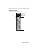
Multi-Channel High-Speed Counter 5 Hardware Features The module’s hardware features are illustrated below.
Multi-Channel High-Speed Counter LEDs The front panel has a total of twelve indicator LEDs.
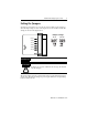
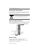
Multi-Channel High-Speed Counter 7 Setting the Jumpers Six jumpers are located in a row on the side of the module. Use the jumpers to select the input voltage for each of the inputs A1, B1, Z1, A2, B2, and Z2. The settings are shown in the figure below. Jumper Settings JP1 (A1 ) 5V dc 4.2-12V dc 24V dc 10-30V dc JP2 (B1) JP3 (Z1) JP4 (A2) (default) JP5 (B2) JP6 (Z2) IMPORTANT For a 12V dc encoder signal, use the 24V dc jumper setting.
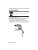
Multi-Channel High-Speed Counter Installing the Module ATTENTION ! Disconnect power before attempting to install, remove, or wire the module. 1. Make sure your SLC power supply has adequate reserve current capacity. The module requires 250 mA at +5V dc. 2. Align the full-sized circuit board with the chassis card guide as shown below. The first slot of the first chassis is reserved for the processor. 3. Slide the module into the chassis until the top and bottom latches catch.
Multi-Channel High-Speed Counter 9 Important Wiring Considerations Use the following guidelines when planning the system wiring for the module: • Install the SLC 500 system in a NEMA-rated enclosure. • Disconnect power to the SLC processor and the module before wiring. • Make sure the system is properly grounded. • Group this module and low-voltage DC modules away from AC I/O or high-voltage DC modules. • Shielded cable is required for high-speed input signals A, B, and Z.
Multi-Channel High-Speed Counter Removing the Terminal Block Remove the terminal block by turning the slotted terminal block release screws counterclockwise. The screws are attached to the terminal block, so the block will follow as the screws are turned out. ATTENTION ! To avoid cracking the removable terminal block, alternate removal of the slotted terminal block release screws. Input and Output Connections Input and output wiring terminals are shown in the figure below.
Multi-Channel High-Speed Counter 11 Differential Encoder Wiring Cable(1) +VDC VS GND COM A A(+) A A(–) B B(+) B B(–) Z Z(+) Z Z(–) Allen-Bradley 845H Series differential encoder Power Suppl Shield Earth shield/housing Connect only if housing is electronically isolated from the motor and ground. (1) Module Inputs Refer to your encoder manual for proper cable type. The type of cable used should be twisted pair, individually shielded cable with a maximum length of 300m (1000 ft.).
Multi-Channel High-Speed Counter Single-Ended Encoder Wiring (Open Collector) cable(1) VS +VDC GND COM R Power Supply (2) A(+) A A(–) B Allen-Bradley 845H Series single-ended encoder B(+) B(–) Z(+) Z Z(–) shield shield/housing Connect only if housing is electronically isolated from the motor and ground. Earth Module Inputs (1) Refer to your encoder manual for proper cable type.
Multi-Channel High-Speed Counter 13 Single-Ended Wiring (Discrete Devices) +VDC COM Power Supply proximity sensor VS A(+) OUT A(–) COM solid-state switch VS OUT B(+) COM B(–) VS OUT R (1) Z(+) COM Z(–) photoelectric sensor with open collector sinking output Module Inputs (1) External resistors are needed if not internal to the sensor. Check your sensor’s documentation. The pull-up resistor (R) value depends on the power supply value.
Multi-Channel High-Speed Counter Electronic Protection The electronic protection of the 1746-HSCE2 has been designed to provide protection for the module from short-circuit and overload current conditions. The protection is based on a thermal cut-out principle. In the event of a short circuit or overload current condition on an output channel, all channels turn off within milliseconds after the thermal cut-out temperature has been reached.
Multi-Channel High-Speed Counter 15 Short-Circuit/Overload Current Diagnostics If a short-circuit or overload current condition occurs on an output channel: 1. The FLT LED flashes, provided that power is applied to the module. 5V dc via backplane and load power via an external supply is required. 2. Fuse status bit (FB1) is set (1) when the fuse is tripped. The module tries to reset the outputs at intervals of 500 ms. During each retry, the fuse status bit is reset (0).
Multi-Channel High-Speed Counter Specifications General Operating Temperature 0°C to +60°C (+32°F to +140°F) Storage Temperature -40°C to +85°C (-40°F to 185°F) Humidity 5 to 95% without condensation Backplane Current Consumption 250 mA at +5V dc (power supply loading) 0 mA at +24V dc Backplane Isolation 1000V dc Maximum Cable Length 300m (1000 ft.
Multi-Channel High-Speed Counter 17 Inputs A, B, and Z Jumper Setting 5V dc 24V dc Nominal Input Voltage 5V dc 24V dc Input Voltage Range 4.2V dc to 12V dc 10V dc to 30V dc On-State Voltage (min.) 4.2V 10V Off-State Voltage (max.) 0.8V 3V Maximum Off-state Leakage Current 100 µA 100 µA Input Current (max.) 8 mA 20 mA Input Current (min.) 6.3 mA 6.3 mA Nominal Input Impedance 500 Ω 1500 Ω Min. Pulse Width 475 ns 475 ns Min. Phase Separation 200 ns 200 ns Max.
Multi-Channel High-Speed Counter Outputs (sourcing) Max. On-State Output Current (per channel) Max On-State Current (per module) 1.0 A at 40°C 1.0 A at 60°C 2.0 A at 40°C 1.5 A at 60°C Max. On-State Voltage Drop 0.5V Max.
Multi-Channel High-Speed Counter 19 Publication 1746-IN002A-US-P
Publication 1746-IN002A-US-P - February 2000 PN 40071-078-01 (A) Supersedes Publication 1746-5.21 - March 1999 © 2000 Rockwell International Corporation. Printed in the U.S.A.