Installation Instructions High-Speed Counter Module (Catalog Number 1746-HSCE) Inside ................................................................................................Page For More Information............................................................................... 3 Hazardous Location Considerations ........................................................ 4 Environnements dangereux .....................................................................
High-Speed Counter Module Important User Information Solid state equipment has operational characteristics differing from those of electromechanical equipment. Safety Guidelines for the Application, Installation and Maintenance of Solid State Controls (Publication SGI-1.1 available from your local Rockwell Automation sales office or online at http://www.ab.com/manuals/gi) describes some important differences between solid state equipment and hard-wired electromechanical devices.
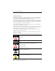
High-Speed Counter Module 3 For More Information Related Publications For Refer to this Document Pub. No. A more detailed description on how to configure and program the High-Speed Counter Module. High-Speed Counter Module User Manual 1746-6.5 A more detailed description on how to install and use your modular SLC™ 500 system.
High-Speed Counter Module Hazardous Location Considerations This equipment is suitable for use in Class I, Division 2, Groups A, B, C, D or non-hazardous locations only. The following WARNING statement applies to use in hazardous locations. WARNING EXPLOSION HAZARD • Substitution of components may impair suitability for Class I, Division 2. • Do not replace components or disconnect equipment unless power has been switched off or the area is known to be non-hazardous.
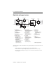
High-Speed Counter Module 5 High-Speed Counter Module Overview The High-Speed Counter Module, Catalog Number 1746-HSCE is an SLC 500 family compatible device except with the 1747-ASB Remote I/O Adapter Module. It can be used with SLC™ 5/02 (and above) processors. The module’s bidirectional counting ability allows it to detect movement in either direction. In addition, x2 and x4 counting modes are provided to fully use the capabilities of high-resolution quadrature encoders.
High-Speed Counter Module Dip Switch and Jumper Locations Counter Input Parameters Rate Period Parameters Z LS LS Filter (JW1) Input Logic Rate Counter Pulse and Direction Operating Mode Logic Reset Parameters Reset Logic Rate Counter Inputs Reset Condition Output Control Parameters Rate Measurement Rate Operating Mode Outputs Output Control Logic 4 Physical Outputs Sequencer Pulse Counter Parameters Output Status Inputs Range Pulse Counter Reset Input Bit Counter Input Parameters In
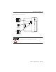
High-Speed Counter Module 7 Default settings are shown below: O N 1 234 SW 2 SW 2 JW 1 JW 1 SW2 Default 10 to 30V dc 3 JW1 1 JW1 Default 10 ms filter O N 1234 SW 1 SW1 Default Single-ended ATTENTION Use a small screwdriver to change dip switch positions. Graphite from pencils will damage the switch.
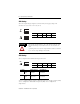
High-Speed Counter Module SW2 Settings Select an output voltage range that coincides with your supply voltage. The selections are 4.5 to 10V dc or 10 to 30V dc. ON OFF 1234 10 to 30V dc 1234 ON OFF Switch 1 2 3 4 Output 0 1 2 3 4.5 to 10V dc All switches of SW2 must be ON or all switches must be OFF. Permanent damage may result if some are ON and some are OFF. ATTENTION Operating in the 10 to 30V dc range with the switches set for the 4.5 to 10V dc range damages the module.
High-Speed Counter Module 9 JW1 Settings Select 300 µs or 10 ms filtering to debounce the limit switch input. Position the jumper as follows: 321 32 1 JW 1 JW 1 10 ms filter 300 µs filter The LS input allows you to make a direct connection to nominal voltage levels of 5, 12, or 24V dc. The ON voltage ranges are as follows: Wiring Terminal ON Range LS (24V dc) 16.5 to 30V dc LS (12V dc) 9.4 to 16.5V dc LS (5V dc) 3.8 to 5.5V dc See page 19 for limit switch wiring instructions.
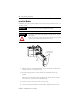
High-Speed Counter Module Install the Module Installation procedures for this module are the same as for any other discrete I/O or specialty module. IMPORTANT Set the dip switches before installing the module. ATTENTION Disconnect power before attempting to install, remove, or wire the module. Make sure your SLC power supply has adequate reserve current capacity. The module requires 320 mA at 5V dc. Top and Bottom Module Release(s) Card Guide 1.
High-Speed Counter Module 11 Remove the Terminal Block The removable terminal wiring block eliminates the need to rewire a module if it is removed from the chassis. Each terminal accepts two #14 AWG wires. ATTENTION Disconnect power before attempting to install, remove, or wire the removable terminal wiring block. To avoid cracking the removable terminal block, alternate the removal of the slotted terminal block release screws.
High-Speed Counter Module Important Wiring Considerations Use the following guidelines when planning the system wiring for the module: • • • • • • • • Install the SLC 500 system in a NEMA-rated enclosure. Disconnect power to the SLC processor and the module before wiring. Make sure the SLC 500 system is properly grounded. Group this module and low-voltage DC modules away from AC I/O or high-voltage DC modules. Shielded cable is required for high-speed input signals A, B, and Z.
High-Speed Counter Module 13 Input and Output Connections Input and output wiring terminals are located on the front of the module, behind the terminal cover. When you connect input and output devices, you must also be concerned with the settings of dip switch SW1 (input connections), dip switch SW2 (output connections), and jumper JW1 (limit switch input connections). The location and description of these are shown on pages 6 through 9. OUTPUT 0 1 2 3 Upper Retaining Screw Maximum Torque = 0.7 to 0.
High-Speed Counter Module Outputs The module features four physical outputs. They can be controlled by the module when certain counter conditions are met, or they can be controlled from the user program (refer to the High-Speed Counter Module User Manual, publication 1746-6.5 for M0:e.0 information). The outputs are bipolar transistors connected in a sinking (open collector sinking) configuration. When the output is energized, it sinks the current. Do not use incandescent lamps as output indicators.
High-Speed Counter Module 15 Encoders The wiring diagrams on the following pages are provided to support the Allen-Bradley encoders you may already have. Differential encoders provide the best immunity to electrical noise.
High-Speed Counter Module Single-Ended Encoder Wiring (Open Collector) cable(1) VS GND + VDC COM Power Supply (3) R Allen-Bradley 845H Series single-ended encoder Shield(2) A A(+) A(-) B B(+) B(-) Z(+) Z(-) Z Belden 9503 or equivalent 305m (1000tft) max length encoder connector housing ON SW1 1 234 OFF (All switches OFF) Module Inputs Earth (1) Refer to your encoder manual for proper cable type and length.
High-Speed Counter Module 17 Single-Ended Encoder Wiring (Sourcing) cable(1) VS + VDC COM GND Power Supply Belden 9503 or equivalent 305m (1000tft) max length A(+) A R B(+) B(-) Z(+) R (3) Z(-) B single ended R encoder(4) (3) A(-) Z (3) Shield(2) SW1 ON 1 2 34 OFF (All switches OFF) Earth Module Inputs (1) Refer to your encoder manual for proper cable type and length.
High-Speed Counter Module Single-Ended Wiring (Discrete Devices) +VDC COM proximity sensor with sourcing output VS OUT COM R1 A(+) A(-) solid-state switch (5V output) VS OUT CO M Power Supply R2 photoelectric sensor with open collector sinking output VS OUT CO M B(+) B(-) Z(+) Z(-) ON 1 2 34 SW1 OFF (All switches OFF) Module Inputs IMPORTANT • This diagram shows the sensors operation from a common power supply. Separate power supplies for each circuit can be used.
High-Speed Counter Module 19 Limit Switch Wiring Connect only one LS input range at a time, or the module will be damaged.
High-Speed Counter Module Specifications General Description Specification Operating Temperature 0° C to +60° C (+32° F to +140° F) Storage Temperature -40° C to +85° C (-40° F to +185° F) Humidity 5 to 95% without condensation Backplane Current Consumption (power supply loading) 320 mA at +5V dc 0 mA at +24V dc Maximum Cable Length(1) 305 m (1000 ft) Agency Certification (when product or packaging is marked) • • CSA certified CSA Class I, Division 2 Groups A, B, C, D • • UL® listed CE
High-Speed Counter Module 21 Limit Switch Input 5V dc 12V dc 24V dc On-State Voltage 3.8 to 5.4V dc 9.4 to 16.5V dc 16.5 to 30V dc Off-State Voltage 0 to 1.2V dc 0 to 2.4V dc 0 to 3.9V dc Input Current minimum nominal maximum 4.6 mA 6.8 mA 9.2 mA Max. Off-State Leakage Current 1 mA (all ranges) Isolation (from backplane) 1500 volts Outputs (Open Collector, Sinking) 4.5 to 10V dc (Switch 2 on) 10 to 30V dc (Switch 2 off) Max. On-State Output Current 16 mA at 4.
High-Speed Counter Module Publication 1746-IN011C-EN-P - April 2005
High-Speed Counter Module 23 Publication 1746-IN011C-EN-P - April 2005
Rockwell Automation Support Rockwell Automation provides technical information on the Web to assist you in using its products. At http://support.rockwellautomation.com, you can find technical manuals, a knowledge base of FAQs, technical and application notes, sample code and links to software service packs, and a MySupport feature that you can customize to make the best use of these tools.