
User guide

Publication 1746-UM006B-EN-P - August 2005
Configuration and Programming 4-37
Input Data File Words -
Sequencer Mode
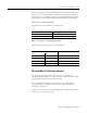
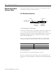
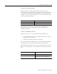
The figure below shows how the input data file words are used. An
explanation of each word follows the figure.
I:e.0 Status Word
I:e.0 Bits 0 and 1
Bits 0 and 1 are reserved and must be reset to 0.
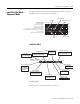
Status Word, Word 0
Bit Number (decimal) 15 14 13 12 11 10 9 8 7 6 5 4 3 2 1 0
I:e.0
Accumulated Count, Word 1
Rate Period Count, Word 2
Rate Measurement Word 3
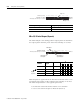
Output Status and Configuration Error Code, Word 4
Next Sequencer Step and Current Sequencer Step Word 5
Reserved, Word 6
Next Sequencer Step Preset, Word 7
I:e.1
I:e.2
I:e.3
I:e.4
I:e.5
I:e.6
I:e.7
Physical
Outputs
Configuration Error Code
Soft Outputs
Next
Sequencer
Step
Current
Sequencer Step
RR
RRRRRRRRRRRRRRRR
RRR
0 = No configuration error
1 = Invalid configuration data
0 = No overflow
1 = Overflow
0 = Nonzero Rate Period Count
1 = Rate Period Count is 0
0 = Invalid rate
1 = Rate valid
0 = No overflow
1 = Overflow
0 = No errors detected
1 = Error detected
0 = No error detected
1 = Overflow/Underflow
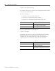
00 = Stopped
01 = Running
10 = Undefined
11 = Hold
0 = False Reset Mode
1 = T
rue Reset Mode
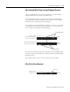
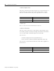
Status Word, Word 0
Bit Number (decimal) 15 14 13 12 11 10 9 8 7 6 5 4 3 2 1 0
I:e.0
Zero
Rate Period Count
Rate V
alid
Rate Counter Overflow
Rate Measurement Overflow
Critical Error
Configuration Error
Pulse Counter State
Overflow/Underflow
Reset Input
R
1 = End of sequence
Sequence Done
RRRR