
User guide

Publication 1746-UM006B-EN-P - August 2005
Configuration and Programming 4-29
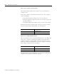
The reset of the counter is edge triggered. It occurs only when all of
the conditions specified become true. If multiple conditions are
selected, the counter is reset on the last event’s 0 to 1 transition. For
example, if Z and LS are selected (011), Z by itself will not trigger the
reset. Z and LS must both be ON.
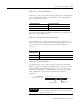
M0:e.1 Bit 8
Bit 8 is reserved and must be reset to 0.
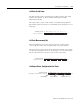
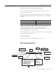
M0:e.1 Bits 9,10,11 - Input Type (Static)
You configure this field to define the counter input type you are
using:
The input type you select determines how the A and B inputs cause
the module’s counter to increment and decrement. For all three input
types, the Z input can be used to force a counter reset. The A, B, and
Z inputs operate with input signals up to a maximum rate of 50 KHz.
IMPORTANT
The time it takes for the counter to reset depends
upon the value it resets to. If the reset value is zero,
the counter resets immediately on the false to true
edge of the reset condition without losing
subsequent counts. If the reset value is nonzero,
there is a delay of up to 500 µs before the reset value
is loaded. Count pulses can be lost if they happen
during the delay time. Refer to Timing Information in
Appendix A.
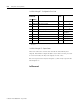
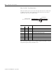
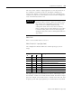
Setup and Control Word bits Input Type
11 10 9
000Invalid - configuration error
001Invalid - configuration error
010Pulse and Direction w/External Control
011Pulse and Direction w/Internal Control
100Quadrature Encoder Input - X1
101Quadrature Encoder Input - X2
110Quadrature Encoder Input - X4
111Up/Down Pulse Inputs