
User guide

Publication 1746-UM006B-EN-P - August 2005
3-4 Installation and Wiring
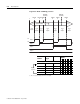
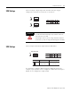
JW1 Settings
Select 300 µs or 10 ms filtering to debounce the limit switch input.
Position the jumper as follows:
The LS input allows you to make a direct connection to nominal
voltage levels of 5, 12, or 24V dc. The ON voltage ranges are as
follows:
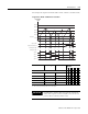
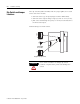
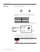
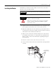
The figure below indicates how to connect a limit switch and 12V dc
supply to the module. Jumper JW1 is placed for a 10 ms debounce.
This input is intended for connection to a limit switch used to reset
the counter. The LS input can be used alone as a reset or in
combination with the Z input, or Soft Reset (refer to M0:e.1/5-7).
Wiring terminal Limit Switch ON range
LS (24V dc) 16.5-30V dc
LS (12V dc) 9.4- 10.5V dc
LS (5V dc) 3.8-5.5V dc
JW1
321
JW1
321
10 ms Filter 300 us Filter
HSCE module
+
–
12V dc
Limit switch
LS (24V dc)
LS (12V dc)
LS (5V dc)
LS COM
JW1
321
wiring terminals
jumper placed for 10 ms filtering
ATTENTION
Only connect one LS input range at a time.
Otherwise, the module will be damaged.