
User guide


Publication 1746-UM006B-EN-P - August 2005
3-2 Installation and Wiring
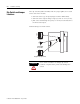
Dip Switch and Jumper
Locations
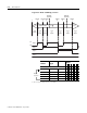
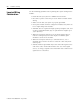
Two dip switches (SW1 and SW2) and one jumper (JW1) are located
on the side of the module.
• SW1 selects the type of input (single ended or differential).
• SW2 selects the output voltage range (4.5-10V dc or 10-30V dc).
• JW1 selects the filtering rate (300 µs or 10 ms) used to debounce
the limit switch input.
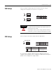
Default settings are shown below:
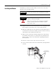
ATTENTION
Use a small screwdriver to change dip switch
positions. Graphite from pencils will damage the
switch.
SW2
JW1
SW1
1234
N
JW1
O
1234
N
O
SW2
SW1
1
3
10-30V dc
SW2 Default
10 ms Filter
JW1 Default
Single Ended Operation
SW1 Default