
User guide

Publication 1746-UM006B-EN-P - August 2005
2-16 Module Operation
Output Start Up and Enabling
When the SLC processor is not in run mode, the module outputs are
disabled. After the SLC processor enters run mode, the module
examines the Direct Output fields (O:e.0/0-7).
All outputs under module control are disabled until after the module
configuration has been completed and the Function Control bit has
been set to 1. If the Function Control bit is returned to 0 the module
controlled outputs will again be disabled. The user program
controlled outputs are not affected by the Function Control bit.
When reset to 0, the Enable Outputs bit (M0:e.1/1) disables module
and user program controlled outputs.
Operating Mode
The Operating Mode field (M0:e.1/14-15) is used to select the
module’s mode of operation. The field is specified as follows:
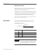
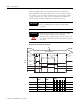
Operating Mode - bits 14, 15
Operating Mode Bits Output Operating Mode
15 14
0 0 invalid
0 1 Range
1 0 Sequencer
11Rate
IMPORTANT
Appendixes D and E contain blank worksheets to
assist you when configuring your module. Appendix
D contains worksheets for Range and Rate Mode
operation. Appendix E contains worksheets for the
Sequencer Mode operation.
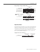
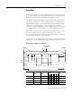
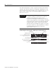
Setup and Control Word, Word 1
Bit Number (decimal)
Operating
Mode bits
15 14 13 12 11 10 9 8 7 6 5 4 3 2 1 0
M0:e.1