
User guide

Publication 1746-UM006B-EN-P - August 2005
Module Operation 2-5
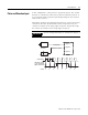
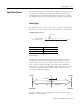
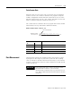
Quadrature Encoder Input
The figure below shows a quadrature encoder connected to inputs A,
B, and Z. The count direction is determined by the phase angle
between input A and input B. If A leads B, the counter increments. If
B leads A, the counter decrements.
The counter resolution can be selected so that the count increments/
decrements on one edge of input A only (X1), on both edges of input
A (X2), or on both edges of input A and input B (X4).
The counter can be reset using the Z input, as described in Counter
Reset Control on page 2-9.
IMPORTANT
The connection of A, B, and Z is critical, refer to
Chapter 3 and Appendix C.
A
B
Z
(Reset input)
Quadrature encoder
module
121110987654321 2345678910 1
654321 12345
1 2 3 2 1
Forward rotation
Reverse rotation
A
B
X1
count
X2
count
X4
count
11
Input A
Input B
Input Z