
User guide


Publication 1746-UM006B-EN-P - August 2005
Application Examples 6-31
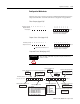
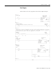
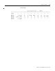
Shown below is a Sequencer Mode Configuration Worksheet for Step
Output information. Based on your application, you enter the Step
Outputs, Step Preset Values, and Reset Value/Maximum Count Value
into the appropriate places on the worksheet. When you begin
programming, you can transcribe the information contained in the
worksheet to your data files. A blank worksheet is supplied in
Appendix E.
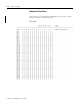
Step Outputs (page 4-33)
Rate Period (decimal) (page 4-33)
M0:e.4
M0:e.5
M0:e.6
M0:e.7
M0:e.8
M0:e.9
M0:e.10
M0:e.11
M0:e.12
M0:e.13
M0:e.14
M0:e.15
Bit Number (decimal) 15 14 13 12 11 10 9 8 7 6 5 4 3 2 1 0
Output
Number
765 4321 0765 4321 0
Step 1 Outputs
Step 3 Outputs
Step 5 Outputs
Step 7 Outputs
Step 9 Outputs
Step 11 Outputs
Step 13 Outputs
Step 15 Outputs
Step 17 Outputs
Step 19 Outputs
Step 21 Outputs
Step 23 Outputs
Step 2 Outputs
Step 4 Outputs
Step 6 Outputs
Step 8 Outputs
Step 10 Outputs
Step 12 Outputs
Step 14 Outputs
Step 16 Outputs
Step 18 Outputs
Step 20 Outputs
Step 22 Outputs
Step 24 Outputs
01110000
00010000
00010000
00010000
00000000
ATTENTION
The module will fault on power-up if you do not
enter a value.
M0:e.16
Rate Period
1 to 255 = 10 ms to 2.55 seconds
001